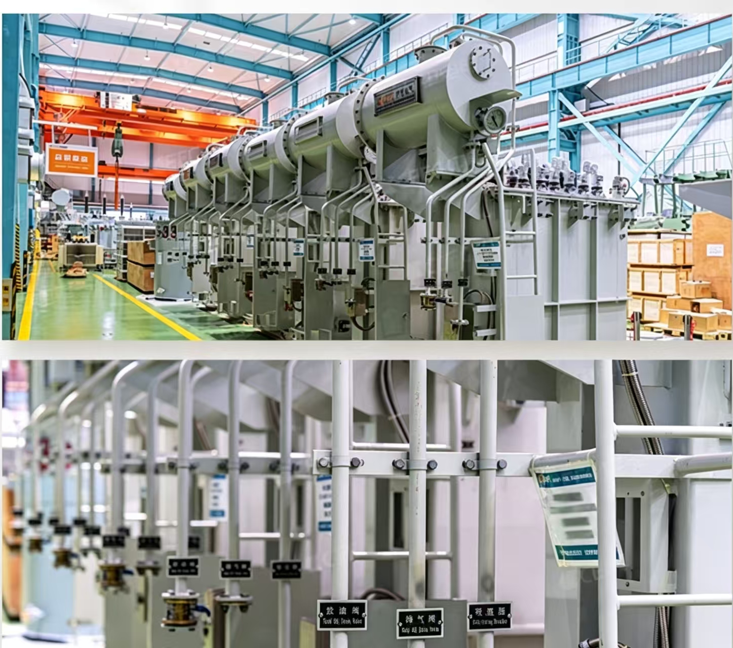
The sf6 ckt breaker serves as a critical protection component within gas-insulated switchgear systems, providing reliable arc suppression and fault isolation in high voltage environments. Understanding how this equipment integrates into GIS architectures is essential for power system engineers, utility planners, and facility managers who need to ensure optimal performance and compliance with modern grid standards. The relationship between sf6 circuit breaker design and switchgear integration determines system reliability, maintenance costs, and operational safety.
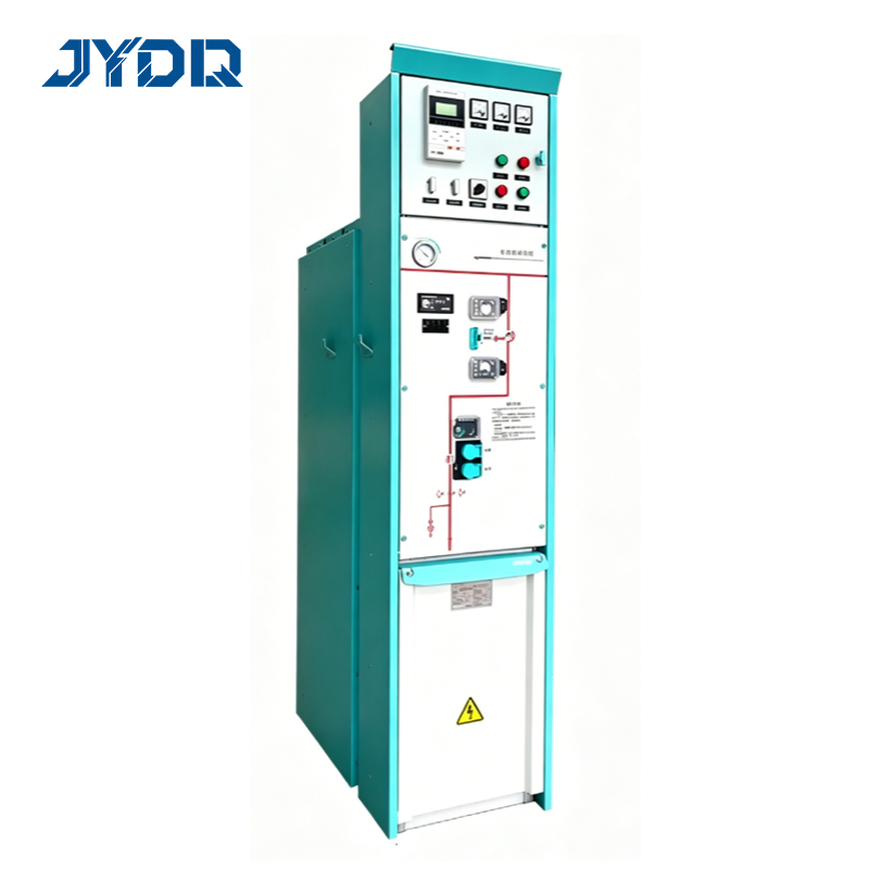
Gas-insulated switchgear systems represent a substantial investment in electrical infrastructure, and the selection of compatible interruption devices directly influences system performance across decades of operation. The sf6 ckt breaker integration process involves mechanical alignment, electrical coordination, thermal management, and maintenance protocols that must all function seamlessly within the GIS enclosure. This comprehensive guide explores the functional requirements, integration principles, and practical considerations that define successful switchgear integration for high voltage applications.
Mechanical and Electrical Requirements for SF6 Circuit Breaker Integration
Physical Alignment and Contact System Design
The sf6 ckt breaker must align precisely with the main bus structure and compartment walls within the GIS framework. Contact systems are engineered to mate with the switchgear integration interface at specific pressures and contact geometries that maintain electrical continuity and minimize resistance losses. The mechanical mounting structure accommodates thermal expansion cycles, vibration from fault currents, and repeated operational sequences without degradation of contact surfaces or compression spring characteristics.
Contact materials in sf6 circuit breaker designs typically employ silver-plated copper alloys or pure silver to ensure low contact resistance across the switchgear integration path. These materials must resist oxidation in the SF6 gas environment and maintain consistent contact force throughout the equipment lifecycle. High voltage ratings demand precise contact gap tolerances to prevent premature wear, flashover risks, and efficiency losses during normal and fault conditions.
SF6 Gas Compatibility and Pressure Coordination
The gas-insulated switchgear system operates at elevated pressure, typically between 4 and 8 bar, to achieve enhanced dielectric strength and compact dimensions. The sf6 ckt breaker must operate reliably within this pressurized environment, maintaining its arc-extinguishing capabilities across the full pressure range specified for the GIS. Pressure regulators and relief valves monitor gas density continuously, and the circuit breaker control system must respond to pressure variations to prevent nuisance trips or operational delays.
Switchgear integration requires that all insulating surfaces and sealing elements withstand SF6 decomposition products that may form during electrical faults. The sf6 ckt breaker contacts and arcing chambers must tolerate trace moisture, metallic particles, and reactive byproducts without loss of dielectric performance. Quality control processes ensure that gas purity standards are maintained throughout manufacturing, installation, and the operational lifetime of the high voltage equipment.
Functional Coordination Within GIS Architecture
Current Interruption and Arc Suppression Mechanisms
The sf6 ckt breaker interrupts fault currents through a combination of contact separation speed, pressure rise within the arcing chamber, and SF6 gas flow directed across the arc. Inside the gas-insulated switchgear system, this interruption must occur within milliseconds to protect downstream equipment and coordinate with protective relays. Switchgear integration ensures that mechanical linkages transmit trip signals reliably and that contact movement velocity remains consistent across thousands of operating cycles.
Arc suppression effectiveness in sf6 ckt breaker designs depends on nozzle geometry, piston acceleration rate, and gas chamber volume. The high voltage environment within GIS compartments necessitates precise calibration of these parameters to achieve rated interrupting capacity while minimizing pressure transients that could stress tank walls or adjacent equipment. Integration testing verifies that the circuit breaker performs correctly under maximum asymmetrical fault conditions and extreme operating temperatures encountered in the field.
Coordination with Control and Protection Systems
Switchgear integration extends beyond mechanical and electrical aspects to encompass control logic coordination and signal transmission. The sf6 ckt breaker control cabinet receives trip commands from microprocessor relays that analyze voltage, current, and frequency data at millisecond intervals. Communication pathways must be hardwired or networked in compliance with IEC 61850 protocols, ensuring deterministic response times and redundancy for critical protection functions.
High voltage switchgear systems typically integrate surge counters, pressure transmitters, and position monitoring switches into the sf6 ckt breaker mechanism. These sensors provide real-time diagnostics that inform maintenance schedules and alert operators to degradation patterns before failures occur. Switchgear integration architecture consolidates data from multiple sensors into a unified platform accessible to control centers and asset management systems.
Thermal Management and Long-Term Reliability in GIS
Heat Dissipation and Operating Temperature Constraints
The sf6 ckt breaker generates internal heat during resistive losses in contacts and damping resistors across fault clearing cycles. Inside the gas-insulated switchgear system, this heat must dissipate through the SF6 gas and conducting surfaces to maintain operating temperatures below design limits, typically 80 to 90 degrees Celsius for sustained ratings. Switchgear integration designs include heat transfer paths from the circuit breaker compartment to the tank wall, where external cooling fans or oil circulation systems remove accumulated thermal energy.
Temperature monitoring within the sf6 ckt breaker and surrounding GIS compartments influences duty cycle classifications and maintenance intervals. High voltage systems operating continuously at elevated loads approach thermal limits faster than those with seasonal or peaking demand patterns. Switchgear integration studies quantify cumulative thermal stress to establish realistic replacement schedules and ensure that insulating materials retain their dielectric strength throughout the equipment lifecycle.
Maintenance Access and Component Replacement Procedures
Successful long-term operation of sf6 ckt breaker systems within GIS requires planned maintenance activities that include contact cleaning, seal inspection, and SF6 gas sampling. Switchgear integration design must facilitate technician access to critical components without full tank depressurization whenever feasible. Modular design principles allow replacement of contact cartridges, control coils, and hydraulic dashpots as individual units, reducing downtime and spares inventory requirements.
Documentation and spare parts management become critical elements of switchgear integration strategies for high voltage installations. Training programs must equip utility personnel with knowledge of the specific sf6 ckt breaker model integrated into their systems, including troubleshooting procedures, gas handling protocols, and emergency protocols for pressure relief or contact replacement. Predictive maintenance programs leverage sensor data and operational history to optimize maintenance intervals and maximize equipment availability.
FAQ
What pressure range must an SF6 circuit breaker maintain within gas-insulated switchgear?
Gas-insulated switchgear systems typically operate at pressures between 4 and 8 bar absolute, and the sf6 ckt breaker must function reliably across this entire range. Switchgear integration specifies minimum and maximum pressure thresholds, with automatic shutdowns or alarms triggered if pressures fall below safety levels. High voltage performance depends on maintaining pressure stability to preserve dielectric strength and interrupting capability.
How does SF6 circuit breaker contact wear affect GIS switchgear reliability?
Contact erosion in the sf6 ckt breaker occurs during each fault clearing event, gradually increasing contact resistance and reducing switchgear integration efficiency. Material transfer from one contact surface to the other creates microscopic surface irregularities that trap SF6 gas decomposition products and moisture. Switchgear integration monitoring systems track contact wear patterns through electrical resistance measurements, allowing preventive replacement before performance degradation compromises high voltage system stability.
Can SF6 circuit breakers be retrofitted into older gas-insulated switchgear installations?
Retrofitting an sf6 ckt breaker into legacy GIS systems requires compatibility verification of mechanical interfaces, electrical ratings, and control signal protocols. Switchgear integration assessments must confirm that the existing compartment geometry accommodates the replacement breaker dimensions and that tank pressure boundaries remain intact after component removal. High voltage testing and type-testing may be required to validate the retrofitted switchgear integration configuration under fault conditions before returning the equipment to service.

 EN