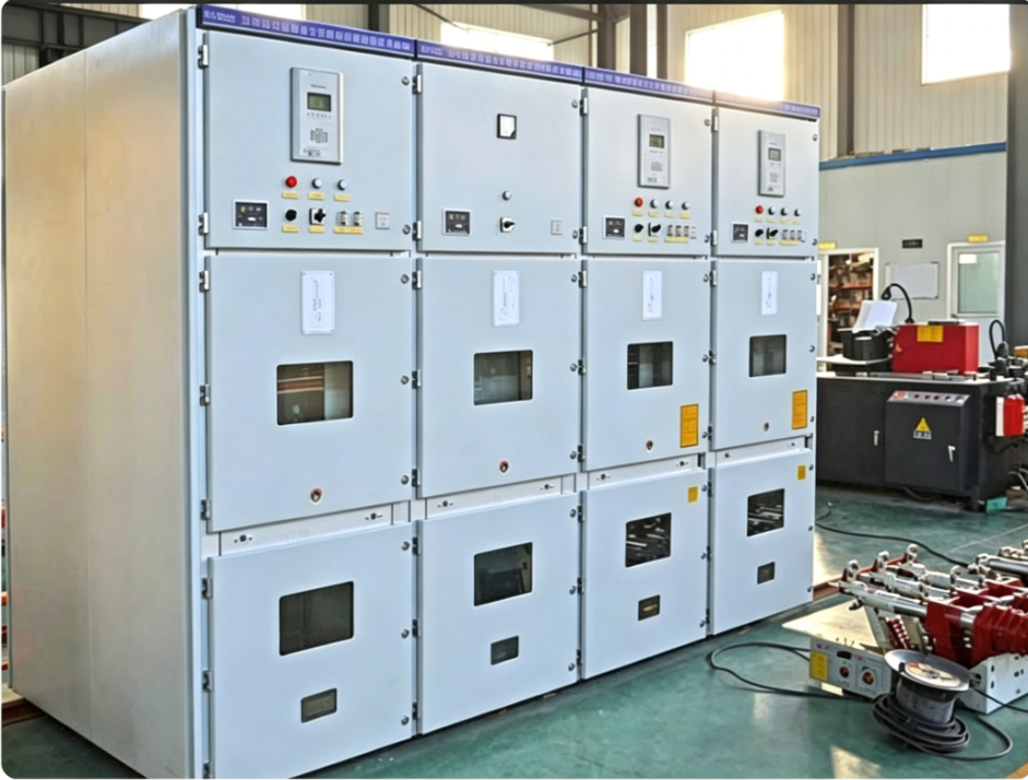
Busbar design stands as one of the most overlooked yet fundamentally important aspects of modern electrical switchgear systems. Many facility managers and electrical engineers focus on protective devices and control circuits without fully recognizing how the underlying busbar architecture directly influences reliability, safety, and operational efficiency. The design of busbars within electrical switchgear determines how current flows through the system, how heat is dissipated, and ultimately how well the entire installation performs under real-world conditions.
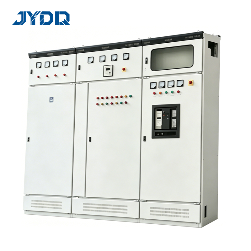
In industrial and commercial applications, the stakes for switchgear design are exceptionally high. Poor busbar design can lead to voltage drops, excessive heat generation, inefficient power distribution, and premature equipment failure. Understanding why busbar configuration matters enables organizations to make informed decisions when specifying or upgrading electrical infrastructure, ultimately protecting both equipment investments and personnel safety.
The Critical Role of Busbar Configuration in Switchgear Systems
How Busbars Function as the Backbone of Current Distribution
Busbars serve as the conductive pathways that carry electrical current throughout switchgear installations. These rigid or flexible conductors must handle substantial electrical loads while maintaining structural integrity and thermal stability. The current capacity of busbars directly determines how much power a switchgear installation can safely transmit. When busbars are undersized or poorly configured, the system becomes a bottleneck that restricts available capacity and creates safety hazards.
The physical arrangement of busbars within a electrical switchgear unit influences electromagnetic field interactions, mechanical stress distribution, and cooling efficiency. Proper spacing, insulation, and support structures ensure that busbars maintain their electrical and mechanical properties even under peak operating conditions or transient fault events. Engineers must account for skin effect at high frequencies, thermal expansion during heavy loading, and magnetic forces that develop during high-current events.
Impact of Material Selection and Cross-Sectional Area
Copper and aluminum remain the most common busbar materials, each offering distinct advantages depending on application requirements. Copper provides superior conductivity and thermal properties, while aluminum offers lighter weight and lower material cost. However, material selection alone does not guarantee adequate performance. The cross-sectional area of busbars fundamentally defines their current capacity and resistance characteristics. A busbar with insufficient cross-sectional area will generate excessive heat, experience voltage drop, and potentially reach unsafe temperatures during normal operation.
Current capacity calculations must account for ambient temperature, ventilation conditions, insulation materials, and duty cycle. Switchgear design standards specify maximum current density limits to prevent thermal degradation. When designers select busbar dimensions too conservatively, they waste material and increase cost. When selections prove inadequate, the system may require expensive retrofitting or replacement. Precision in busbar sizing based on realistic load analysis ensures switchgear design meets both performance and economic objectives.
Thermal Management and Safety Considerations
Heat Dissipation as a Primary Design Driver
Heat generation in busbars follows fundamental electrical principles; current flowing through resistive conductors converts electrical energy to thermal energy. The relationship between current, resistance, and heat output means that even modest increases in current can create significant temperature rises. Switchgear design engineers must ensure that busbar geometry and installation methods facilitate adequate heat dissipation to surrounding enclosure structures and air. Poor thermal management can trigger nuisance trips in protective devices, accelerate insulation degradation, and create fire hazards.
Effective thermal design in switchgear installations requires careful consideration of air circulation, fin arrangements, and material conductivity. Busbars must be positioned to allow convective cooling while maintaining safe working distances from personnel and combustible materials. Some industrial applications benefit from forced ventilation or liquid cooling systems integrated into switchgear design. Temperature monitoring through thermographic surveys or embedded sensors can verify that actual operating conditions match design assumptions.
Mechanical Stress and Fault Current Handling
When short-circuit faults occur, extremely high currents flow through busbars for milliseconds before protective devices interrupt the circuit. These transient currents generate powerful electromagnetic forces that attempt to physically separate or compress conductors depending on current direction. Switchgear design must account for electro-mechanical forces that can damage busbars, bend support structures, or create dangerous conditions. Adequate spacing between parallel conductors and robust mechanical support systems prevent physical distortion during fault events.
The current capacity specifications for busbars must include consideration of both continuous operating limits and momentary fault withstand ratings. Switchgear design standards define acceptable mechanical stress levels and require verification through calculation or testing. Undersized busbars or inadequate support structures may handle normal operating currents safely but fail catastrophically during fault conditions. This distinction between continuous and fault ratings emphasizes why comprehensive switchgear design analysis cannot rely on steady-state assumptions alone.
Practical Implementation and System Integration
Modular Design Flexibility and Scalability
Modern switchgear design increasingly incorporates modular busbar arrangements that enable capacity expansion without complete system replacement. Tiered busbar configurations allow facilities to add new circuits or upgrade capacity as operational requirements evolve. Current capacity planning becomes more strategic when the electrical switchgear infrastructure supports modular growth. Engineers can specify initial configurations that meet current needs while reserving capacity in the main busbar section for future expansion.
Standardized busbar dimensions and connection methods streamline manufacturing, installation, and maintenance of switchgear systems. When busbar design follows industry conventions, replacement components become readily available, and troubleshooting follows familiar patterns. Modular approaches also simplify coordination with auxiliary equipment such as metering transformers, surge protection devices, and energy management systems that connect to busbar structures.
Coordination with Protection and Control Systems
Switchgear design excellence requires seamless integration between busbars, protective relays, and control circuits. The switchgear design process must verify that protective devices respond appropriately to the electrical characteristics created by specific busbar configurations. Voltage drop characteristics influenced by busbar resistance affect relay sensitivity and accuracy. Current distribution among parallel paths depends on busbar impedance matching. Protective coordination studies must account for these busbar-dependent electrical parameters to ensure selective, reliable protection.
Advanced switchgear design now incorporates communication networks that monitor voltage, current, and temperature conditions throughout the busbar system. Digital relays process this data to optimize load distribution, detect incipient faults, and trigger predictive maintenance interventions. This integration requires that busbar design provides adequate measurement points and supports equipment mounting locations without compromising structural or thermal performance.
FAQ
What determines the current capacity of busbars in electrical switchgear?
Busbar current capacity depends on the cross-sectional area of the conductor material, the material itself (copper versus aluminum), ambient temperature, allowable temperature rise, and cooling method. Switchgear design standards define maximum current density limits that prevent thermal damage. Engineers calculate busbar dimensions by dividing required current capacity by the allowable current density to determine the necessary cross-sectional area. Actual current capacity is then verified considering the specific installation environment and ventilation conditions within the switchgear enclosure.
How does busbar design affect overall electrical switchgear reliability?
Busbar design directly influences reliability by determining whether the electrical switchgear can handle full operating loads without excessive heat generation, voltage drop, or mechanical stress. Poor switchgear design leading to undersized busbars creates conditions that accelerate insulation degradation, increase failure rates of connected equipment, and reduce overall system availability. Robust switchgear design with properly sized busbars maintains stable operating conditions, reduces stress on protective devices, and extends the service life of the entire installation. Current capacity considerations throughout switchgear design ensure that the system remains within safe operating limits under all anticipated conditions.
Why is thermal management critical in switchgear design?
Thermal management in switchgear design prevents insulation damage, reduces equipment stress, and maintains safety margins. Excessive temperatures caused by poor busbar design or inadequate cooling can degrade insulation properties, trigger premature device failures, and create fire hazards. The current capacity of busbars must be matched to the cooling capability of the switchgear design to ensure that operating temperatures remain within acceptable limits. Proper ventilation, adequate spacing between conductors, and material selection all contribute to effective thermal management in electrical switchgear installations.

 EN