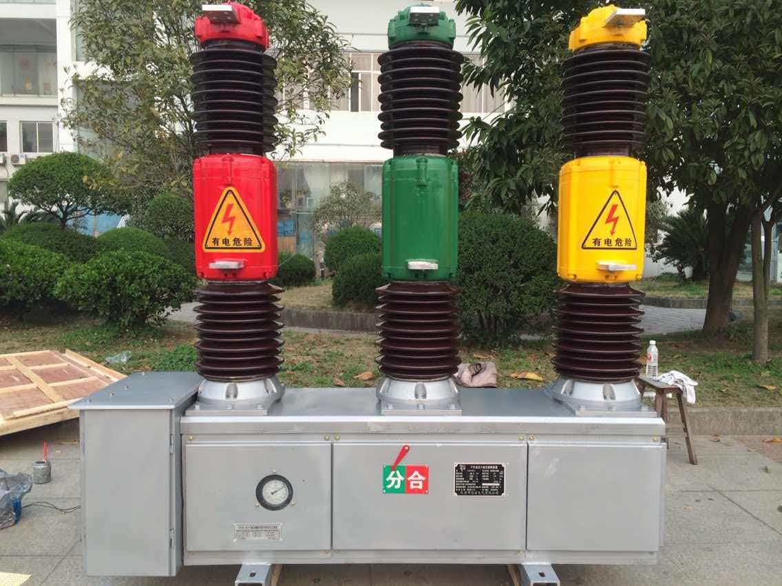
Coordinating high-voltage and low-voltage sections within a compact substation requires precision, planning, and a deep understanding of electrical system integration. As industrial facilities demand more efficient power distribution solutions, the role of a prefabricated box-type transformer has become central to achieving reliable HV LV separation and operational safety in space-constrained environments. Modern substations must balance performance, safety compliance, and spatial efficiency, making proper coordination between high-voltage and low-voltage components essential for long-term reliability.
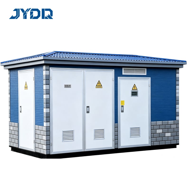
The integration of switchgear, transformers, and protection systems in a compact substation demands careful attention to electrical hierarchy, thermal management, and maintenance accessibility. A well-designed compact substation ensures that HV LV coordination occurs without compromising equipment performance or creating operational bottlenecks. Understanding the technical principles behind this coordination helps facility managers, electrical engineers, and procurement specialists select and deploy the right solutions for their specific industrial or commercial applications.
Understanding HV LV Separation in Compact Substations
The Role of Electrical Hierarchy in Compact Designs
High-voltage and low-voltage sections operate at fundamentally different voltage levels, requiring distinct physical and electrical separation to prevent faults, arc faults, and safety hazards. In a compact substation, this separation must be achieved within minimal footprint constraints. The HV LV separation starts with physical barriers, insulation coordination, and spatial layout that prevents cross-contamination of electrical fields. Proper spacing between high-voltage and low-voltage equipment reduces the risk of unintended electrical paths and ensures that fault current in one section does not cascade into the other.
Insulation Coordination and Protection Layers
Insulation coordination ensures that protective devices respond appropriately to overvoltages before insulation breaks down. Within a compact substation, this requires careful specification of cable routes, busbar arrangements, and the physical positioning of switchgear. The prefabricated box-type transformer design enables manufacturers to pre-engineer insulation distances, barrier heights, and protective partitions during factory assembly, reducing field-installation risks and ensuring compliance with standards like IEC 61936 and IEEE C37.122. This factory-controlled approach guarantees that HV LV coordination meets design specifications consistently across different installation sites.
Technical Design of Compact Substation Layouts
Compartmentalization and Functional Zones
Modern compact substations employ compartmentalized designs that physically separate the transformer tank, switchgear, and control cabinets into distinct functional zones. This modular approach allows engineers to optimize each zone independently while maintaining clear HV LV boundaries. The high-voltage primary side houses incoming feeders, primary switchgear, and transformer primary windings, while the low-voltage secondary side contains distribution switchgear, metering, and outgoing circuits. Switchgear placement becomes critical because it must intercept faults on each voltage level without allowing transient overvoltages to propagate across the HV LV interface. The compartmentalized layout also improves maintenance accessibility and reduces the risk of accidental contact with live parts during routine operations.
Thermal and Spatial Efficiency
Compact substations must dissipate transformer heat without compromising equipment reliability or creating hot spots that accelerate insulation degradation. Ventilation pathways must be sized so that cooling air can flow freely around the transformer core and windings while preventing entry of moisture and contaminants into the switchgear compartments. A well-designed prefabricated box-type transformer incorporates integrated cooling channels, sealed feedthroughs, and thermal management features that maintain insulation integrity. The compact substation layout must also account for thermal stratification, where hot air rises and could degrade low-voltage control circuits if they are positioned directly above the transformer. Proper vertical separation and ducting ensure that HV LV coordination includes thermal stability as a design parameter rather than an afterthought.
Switchgear Integration and Protective Coordination
Overcurrent and Short-Circuit Protection Strategy
Switchgear in a compact substation must provide coordinated protection across both the high-voltage and low-voltage sides, with each device tuned to detect faults at its respective voltage level. The HV side typically uses current transformers and overcurrent relays to detect high-voltage faults, while the LV side uses direct measurement or lower-ratio CTs for sensitivity to low-voltage events. The coordination strategy must ensure that a fault on the low-voltage side is cleared by LV switchgear before current reaches dangerous levels, and that a high-voltage fault is isolated by HV switchgear without affecting the low-voltage circuit. This discrimination requires careful setting of relay curves, time delays, and instantaneous thresholds. The prefabricated box-type transformer design supports this coordination by providing standardized, pre-tested connection points and CT ratios that eliminate field-engineering variables and reduce the risk of misapplication.
Transient Overvoltage Control and Surge Protection
Lightning strikes, switching transients, and fault transients can generate overvoltages that exceed steady-state insulation ratings, potentially causing flashover between HV and LV compartments if surge protection is inadequate. Proper HV LV coordination requires surge arresters on the high-voltage primary side and coordinated surge protection on the low-voltage secondary to limit overvoltages to levels within the insulation withstand capability of cables and equipment. The compact substation must incorporate surge-protective devices close to their protected equipment to minimize traveling-wave effects. Switchgear in compact designs benefit from pre-mounted surge arresters and coordinated protection schemes that are validated during factory testing, ensuring that actual field performance matches design assumptions.
FAQ
How does a prefabricated box-type transformer improve HV LV coordination compared to site-assembled equipment?
Factory assembly of a prefabricated box-type transformer ensures that insulation distances, barrier positioning, grounding connections, and protection device mounting are standardized and pre-tested. This eliminates field-assembly variability that could compromise HV LV separation. The manufacturer can validate the complete assembly against standards before shipment, reducing the risk of coordination failures caused by improper installation. Site-assembled components rely on field engineers to achieve the same spacing and coordination, introducing human error and inconsistency across projects.
What role does switchgear placement play in compact substation HV LV coordination?
Switchgear must be positioned to intercept faults and limit fault current progression between voltage levels. In a compact substation, switchgear placement is constrained by spatial limitations, so the design must prioritize protective function over convenient accessibility. Modern switchgear is engineered to operate reliably in compact compartments with optimized cable routing and busbar positioning. Switchgear coordination ensures that protective devices respond in a predictable sequence, with primary protection acting first and backup protection engaging only if primary protection fails, preventing cascading failures across the HV LV interface.
Can a compact substation maintain adequate HV LV separation in extremely tight spaces?
Yes, provided the design follows standards such as IEC 61936 and incorporates compartmentalization, physical barriers, and insulation coordination. A prefabricated box-type transformer achieves tight spacing because factory engineering can optimize every component position and connection. However, extremely tight spaces may impose limitations on cooling, maintenance access, or future upgrades. Engineers must balance spatial efficiency with operational safety and maintainability, ensuring that HV LV coordination does not degrade under real-world operating conditions or during emergency maintenance procedures.

 EN