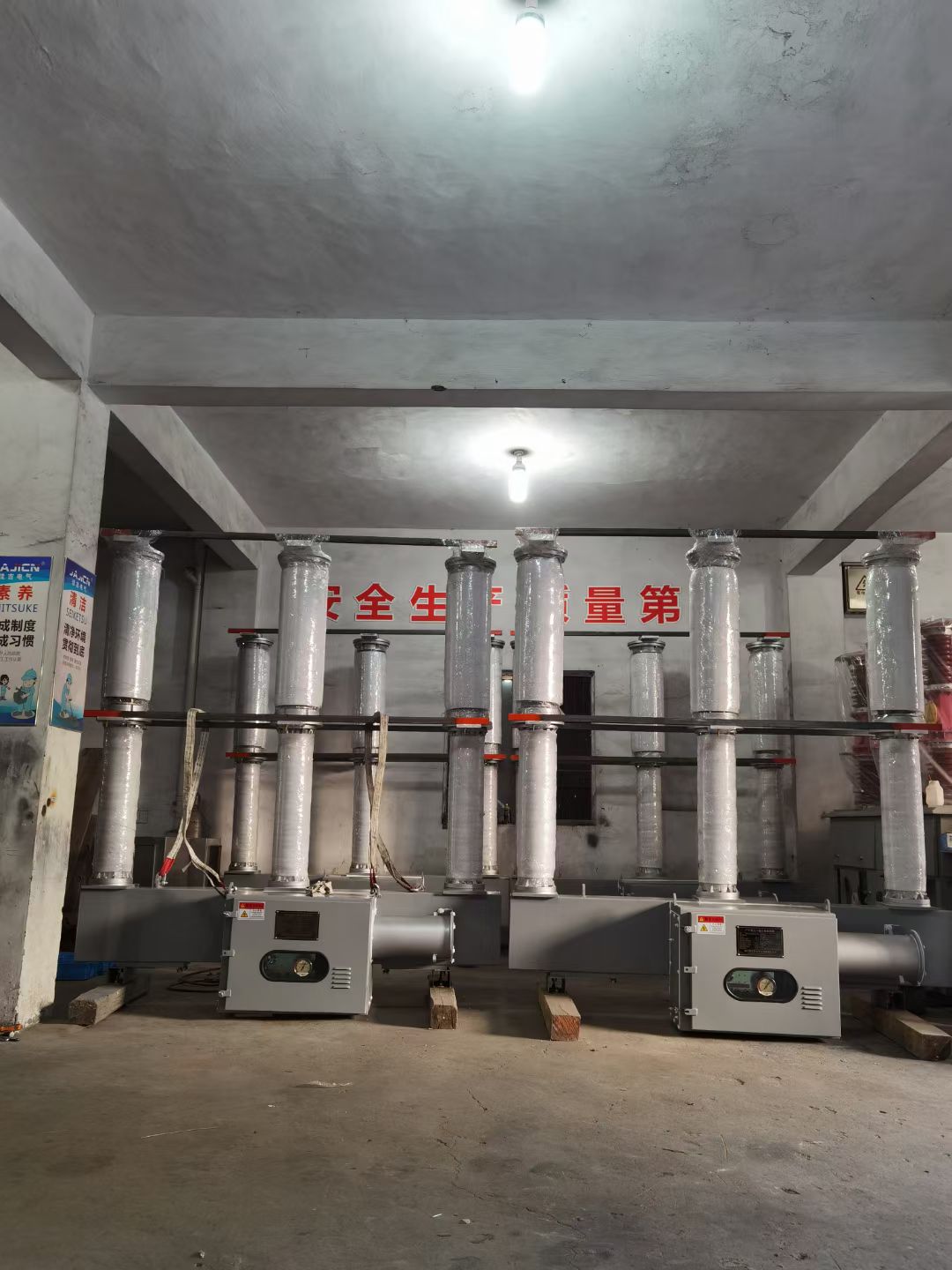
Coordinating switchgear, transformers, and circuit breakers in one system requires careful planning, precise engineering, and a deep understanding of how these critical components interact. In industrial and commercial power distribution networks, these three elements form the backbone of electrical system reliability, protection, and performance. Without proper integration, even high-quality individual components can create safety hazards, operational inefficiencies, and unexpected downtime.
The coordination of switchgear, transformers, and circuit breakers is not simply about connecting components together. It involves electrical calculations, fault analysis, protective device sequencing, and system architecture decisions that determine how power flows through your facility and how quickly the system responds to electrical faults. This comprehensive guide explains the principles, methods, and practical steps necessary to achieve effective coordination in modern electrical systems.
Understanding the Role of Each Component
Switchgear as System Control
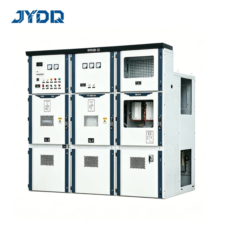
Switchgear serves as the control and protection center of electrical distribution networks. It includes disconnects, bus structures, protective relays, and monitoring systems that manage power flow and isolate faulty sections. Modern switchgear designs incorporate advanced metering, communication capabilities, and fault detection features that enable real-time system assessment. The switchgear you select determines the voltage level, current rating, and response characteristics of your entire electrical architecture.
Transformers as Voltage Interface
Transformers step voltage up or down between different system levels and provide electrical isolation between circuit sections. Each transformer has impedance characteristics that affect fault current levels and protective device coordination. The transformer sizing, winding connection, and tap settings directly influence how protective relays and circuit breakers respond to abnormal conditions. Transformer integration begins during system design and continues through operational adjustments and maintenance cycles.
Circuit Breakers as Fault Response
Circuit breakers detect and interrupt fault currents before they damage equipment or create safety risks. Each circuit breaker has specific trip characteristics, response times, and current ratings that must align with system voltages, transformer impedances, and load requirements. Circuit breaker coordination ensures that only the nearest protective device trips during a fault, isolating the problem while keeping the rest of the system energized and operational.
Core Coordination Principles
Selective Coordination Logic
Selective coordination means that when a fault occurs, only the circuit breaker closest to the fault point should trip, while all upstream and downstream protective devices remain functional. This principle requires that each protective device in the system have deliberately different trip curves, thresholds, or time delays. Achieving selective coordination between a transformer's protection and circuit breaker protection requires detailed coordination studies that map fault currents across multiple scenarios and voltage levels.
Impedance Alignment
The impedance of transformers fundamentally affects fault current levels throughout the system. A lower impedance transformer produces higher fault currents, requiring circuit breakers with higher interrupting ratings and faster response. A higher impedance transformer limits fault currents, allowing smaller circuit breakers but potentially affecting voltage stability. System designers balance transformer impedance with switchgear capabilities and circuit breaker ratings to achieve coordination while maintaining system performance across steady-state and fault conditions.
Time-Current Coordination
Each protective device operates within a specific time-current envelope. Circuit breakers on the load side of a transformer must trip faster than those on the source side, creating a time-delay margin that ensures selective coordination. Integration of switchgear with transformer protection and circuit breakers requires plotting trip curves on logarithmic time-current graphs to verify that protective bands do not overlap inappropriately. This technical analysis prevents nuisance trips while ensuring that faults are cleared before equipment damage occurs.
Integration Methods and Practical Steps
System Study and Fault Analysis
Begin coordination planning with a comprehensive fault analysis study that calculates three-phase and single-phase fault currents at every major junction in your system. This study establishes the actual fault current magnitude that protective devices will experience, informing the selection of switchgear interrupting ratings, circuit breaker trip settings, and transformer impedance specifications. Modern analysis software integrates transformer models, switchgear characteristics, and circuit breaker trip curves to predict system behavior under fault conditions and verify coordination across all voltage levels.
Protective Device Selection
Once fault currents are determined, select protective devices that can interrupt those currents and coordinate with adjacent devices. For each transformer, choose a circuit breaker with an interrupting rating exceeding the calculated fault current. Verify that the circuit breaker trip curve can be adjusted or selected to create appropriate time-current margins with upstream and downstream protective devices. The transformer's impedance, combined with circuit breaker ratings and trip settings, determines the overall coordination strategy for that section of the system.
Testing and Validation
Before commissioning, conduct comprehensive testing to verify coordination between protective devices. Simulation software can model various fault scenarios and confirm that trip sequences occur as designed. Field testing validates that physical devices operate according to specifications and that communication between protective relays and switchgear functions correctly. Ongoing monitoring after commissioning allows detection of component drift or degradation that could compromise coordination, enabling corrective maintenance before problems emerge.
FAQ
Why is coordination between switchgear and circuit breakers essential?
Coordination ensures that faults are isolated quickly without interrupting power to healthy system sections. Without proper coordination, multiple protective devices might trip simultaneously, causing widespread outages instead of localized isolation. This selectivity minimizes downtime, reduces equipment damage, and maintains system stability during fault events, protecting both assets and personnel safety.
How does transformer impedance affect circuit breaker coordination?
Transformer impedance directly determines fault current levels downstream of the transformer. Lower impedance transformers produce higher fault currents that may exceed circuit breaker ratings, requiring upsized protective equipment. Higher impedance reduces fault currents but may compromise voltage stability. Designers choose transformer impedance as part of the overall coordination strategy to balance fault protection with system performance requirements.
What role does switchgear play in managing integrated protection?
Switchgear provides the infrastructure for protective relays, metering equipment, and monitoring systems that detect faults and coordinate with circuit breakers. Modern switchgear includes communication features enabling real-time data sharing with circuit breaker trip units, allowing precise coordination. Switchgear also provides physical separation of circuits, bus structures for power distribution, and isolation capabilities that support the overall protection coordination strategy across all system voltage levels.

 EN