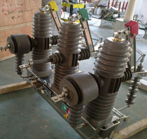
Ensuring the safety and reliability of electrical distribution systems depends fundamentally on comprehensive testing protocols for high and low voltage switchgear. These critical components form the backbone of industrial power systems, managing fault protection, load switching, and system isolation across manufacturing facilities, utilities, and infrastructure networks. Without rigorous switchgear testing during manufacturing and installation phases, equipment failures can cascade into operational shutdowns, safety hazards, and substantial financial losses. Understanding which tests should be performed, why they matter, and how they contribute to system integrity is essential for engineers, procurement professionals, and facility managers responsible for electrical infrastructure.
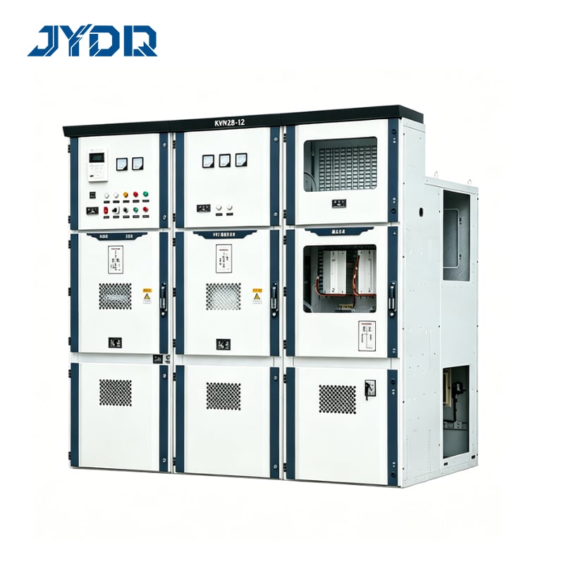
The regulatory landscape and international standards governing switchgear performance have evolved significantly over the past two decades. Standards such as IEC 62271 establish baseline requirements for switchgear design, manufacturing, and field testing. However, regulatory compliance alone does not guarantee operational performance or longevity. A comprehensive quality control approach requires multiple layers of switchgear testing, each designed to validate specific functional and safety attributes.
Dielectric and Insulation Integrity Tests
Insulation Resistance and Voltage Withstand Testing
Dielectric strength represents the most fundamental characteristic of switchgear performance. Insulation resistance tests measure the ability of insulation materials to resist electrical current flow under specified voltage conditions. These tests validate that insulation has not been compromised during manufacturing, transportation, or installation. High and low voltage switchgear must undergo high-voltage withstand testing, commonly called dielectric withstand or factory acceptance testing. This switchgear testing procedure applies a voltage significantly higher than nominal operating voltage for a defined duration, typically one minute, to confirm that the insulation will not break down during normal service.
The test report documenting insulation resistance results must include measurements taken at multiple points within the switchgear assembly, including phase-to-ground, phase-to-phase, and between fixed and moving components. Quality control standards require that resistance values exceed minimum thresholds specified by equipment design ratings. For medium-voltage switchgear, insulation resistance typically must exceed several megaohms before and after temperature conditioning.
Partial Discharge Detection
Partial discharge (PD) testing identifies incipient faults within the insulation system before they develop into catastrophic failures. Partial discharge occurs when localized electrical stress creates ionization in small voids or defects within the insulation material. Modern switchgear testing protocols employ ultrasonic and electromagnetic methods to detect partial discharge activity during voltage application. A quality control test report must document PD measurements taken at multiple voltage levels, typically from 50% to 100% of the withstand voltage.
The significance of partial discharge detection lies in its predictive capability. Equipment exhibiting low levels of PD at factory acceptance testing may develop failures months or years into service life. Conversely, equipment with zero detectable PD provides greater confidence in long-term reliability. Modern test report formats include PD trend analysis and acceptance criteria aligned with international standards.
Mechanical and Functional Performance Tests
Contact Resistance and Current Carrying Capability
High and low voltage switchgear must safely carry rated current without generating excessive heat at contact interfaces. Contact resistance testing measures the electrical resistance across fixed and moving contacts under full-rated current conditions. This switchgear testing validates that contact surfaces are clean, properly aligned, and capable of carrying current without degradation or thermal runaway. The test report typically documents contact resistance values recorded after initial current application and after thermal cycling to simulate extended service conditions.
Current distribution testing ensures that load current flows uniformly across all parallel contact paths. Uneven current distribution concentrates thermal stress on a subset of contacts, accelerating degradation and potentially creating fire hazards. Modern switchgear testing procedures employ thermography and resistance mapping to identify contact regions experiencing elevated temperatures or resistance values outside specification. Quality control personnel reviewing test reports must understand that acceptable contact resistance under no-load or light-load conditions provides no indication of thermal performance under full-rated current.
Operating Mechanism and Trip Testing
The mechanical operating mechanism of high and low voltage switchgear must function reliably through hundreds or thousands of cycles over its operational lifetime. Switchgear testing protocols include mechanism function tests where the equipment is opened and closed multiple times under both manual and automatic control. The test report documents the force required to operate the mechanism, the speed of contact separation, and the consistency of performance across repeated cycles. Quality control evaluation ensures that mechanism friction, wear, or misalignment does not prevent reliable operation when operators or automatic trip devices activate the switchgear during fault conditions.
Trip testing validates that protection devices respond correctly when fault current flows through the switchgear. For low-voltage circuit breakers and medium-voltage vacuum interrupters, trip testing subjects the equipment to multiples of rated current to confirm that thermal and magnetic trip elements respond within specified timeframes. A comprehensive test report includes current-time curves demonstrating that trip response aligns with protective coordination requirements.
Arc Performance and Interruption Capacity Tests
Fault Current Interruption Capability
The ability of high and low voltage switchgear to safely interrupt fault current represents its most critical performance attribute. Arc interruption testing subjects the switchgear to fault currents at levels approaching its rated interrupting capacity, confirming that the equipment can extinguish the arc and isolate the fault without equipment damage, fire, or personnel hazard. Modern switchgear testing procedures apply three-phase fault current in sequence, with test report documentation showing that the equipment successfully interrupts current at each phase without exceeding specified pressure rise or arc duration.
The test report for arc interruption capability must include detailed measurements of arc voltage, current decay rate, and time to current zero. These parameters inform the design of downstream protective coordination and confirm that the switchgear will not propagate faults to upstream equipment when it operates. Quality control engineers comparing switchgear testing results to international standards such as IEC 62271-100 ensure that performance margins exist beyond rated capacity, providing confidence that the equipment will function safely even under non-standard fault conditions.
Environmental Stress and Thermal Performance
The operating environment introduces thermal, mechanical, and environmental stresses that must be simulated during switchgear testing to predict field performance. Temperature cycling tests expose the equipment to multiple cycles from minimum to maximum ambient temperature and back, assessing whether thermal expansion and contraction introduce contact misalignment, insulation degradation, or mechanism wear. The test report documents performance after thermal cycling to confirm that no deterioration occurs in dielectric strength, contact resistance, or mechanical function.
High and low voltage switchgear installed in industrial, utility, or harsh environments may face contamination from dust, salt spray, or corrosive gases that degrade performance over time. Advanced switchgear testing protocols include salt fog or humidity cycling to evaluate corrosion resistance of metallic components and degradation of insulation materials exposed to aggressive environments. The test report must document whether surface treatments, material selections, or enclosure design effectively protect internal switchgear components from environmental attack.
FAQ
What is the primary purpose of switchgear testing before installation?
Switchgear testing before installation validates that the equipment was manufactured to design specifications and will function reliably during operation. The test report provides objective evidence that insulation integrity, contact performance, mechanism reliability, and arc interruption capability meet or exceed applicable standards. This factory acceptance testing protects the purchaser by confirming that the equipment will deliver the expected performance, safety, and operational life before installation costs are incurred. Quality control testing also identifies manufacturing defects or shipping damage that might otherwise remain hidden until the equipment experiences an actual fault condition in the field.
How frequently should high and low voltage switchgear undergo field testing?
Field testing of installed high and low voltage switchgear typically occurs annually or according to utility and manufacturing facility maintenance schedules. Routine switchgear testing includes insulation resistance measurements, contact resistance checks, and mechanism function verification to detect degradation or misalignment developing over time. The test report from field assessments establishes baseline performance data and trends that indicate whether maintenance or component replacement is needed before failure occurs.
What information should a comprehensive switchgear test report include?
A thorough test report for high and low voltage switchgear documents all measurements, acceptance criteria, and results for the complete range of factory tests, including insulation resistance, dielectric withstand, partial discharge, contact resistance, mechanism function, and arc interruption tests. The test report must include date, equipment serial number, test technician identification, and reference to the applicable standards under which testing was performed. Quality control acceptance criteria and actual measured values must be clearly presented, with notation of any test failures, retesting procedures, or deviations from standard protocols. This comprehensive documentation enables future maintenance personnel and engineers to understand the equipment's baseline condition and trend performance changes that might indicate maintenance needs or potential failure modes developing over time.

 EN