Planning cable connections around a dry type transformer requires careful attention to electrical safety, spatial constraints, and regulatory compliance. A dry type transformer operates without liquid coolant, making it ideal for indoor installations, but this design also demands precise cable routing and connection strategies to prevent interference, heat buildup, and operational failure. Understanding the relationship between transformer terminal layout and your cable infrastructure is essential for any industrial facility planning an upgrade or new installation.
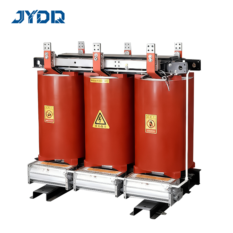
The foundation of effective cable connection planning begins with understanding your transformer's terminal configuration. Most modern installations center on the terminal layout provided by the manufacturer, which specifies input, output, and grounding points. Proper cable connection practices ensure that your electrical system operates efficiently while maintaining safety standards that protect equipment and personnel. This guide walks through the critical steps needed to coordinate cables, manage space, and achieve a reliable installation.
Understanding Terminal Layout and Connection Points
Primary and Secondary Terminal Configuration
Every dry type transformer features distinct terminal groupings that define how incoming power connects to outgoing loads. The primary terminals accept the high-voltage input, while secondary terminals distribute the transformed voltage to your facility's distribution panels. Terminal layout varies by transformer design, so consulting the manufacturer's wiring diagram is non-negotiable. The cable connection strategy must account for these terminal locations, ensuring that conductors can be routed without sharp bends, excessive tension, or contact with hot surfaces.
Grounding terminals represent another critical element of terminal layout design. These provide the return path for fault currents and must connect to your facility's ground grid with proper gauge and routing. Misalignment between cable sizing and terminal specifications can create bottlenecks or introduce unwanted resistance. When planning cable connection points, always verify that terminal lugs match your conductor gauge and that the installation procedure follows the transformer manufacturer's guidelines.
Voltage Rating and Cable Gauge Alignment
The voltage rating of your dry type transformer directly influences cable gauge requirements. Higher voltage installations demand thicker conductors to manage current loads safely. Cable connection planning must ensure that your selected wire gauge aligns with both the transformer's rated capacity and the distance from the transformer to distribution equipment. Undersized cables generate excessive heat, while oversized cables waste material and complicate routing. A professional load calculation determines the correct gauge, which then informs your overall installation strategy.
Spatial Planning and Cable Routing
Clearance Requirements Around the Transformer
Dry type transformers require minimum clearance distances for ventilation and access. These clearances directly affect how you route cable connections around the equipment. Most installations require at least 12 inches on sides and top surfaces, depending on local electrical codes. When planning cable connection routes, avoid running conduit directly against the transformer housing, as this restricts airflow and accelerates insulation degradation. Instead, use cable trays positioned 18 to 24 inches away from the transformer body, allowing maintenance access while protecting cables from physical damage.
The terminal layout often positions connection points on the front or side of the transformer enclosure, which influences whether you route cables up, down, or laterally from the device. Evaluate your facility layout early to determine whether cables feed from above, below, or the same level as the transformer. This decision affects conduit bend radius requirements, support structure placement, and future maintenance accessibility. Poor spatial planning forces sharp bends in cable runs, increasing voltage drop and creating safety hazards during installation or repair work.
Separation and Segregation Best Practices
Industrial facilities often operate multiple power systems, and cable connection routing must maintain proper separation between high-voltage and low-voltage circuits. Keep primary-side cables for your dry type transformer physically distinct from secondary-side and control wiring by using separate cable trays or maintaining minimum spacing. This separation minimizes electromagnetic interference and prevents accidental contact between conductors at different potentials. National Electrical Code standards typically require 6 inches of separation or physical barriers where crossing is unavoidable.
Additionally, segregate AC and DC circuits when both exist in your facility. Cable connection planning should create dedicated routes for transformer-related cables, clearly marked and documented for future technicians. Color-coded conduit or cable jackets help operators identify circuits at a glance, reducing the risk of connection errors during maintenance or emergency shutdown scenarios. Documentation of these routes becomes invaluable if relocation or expansion becomes necessary later.
Installation Best Practices and Final Connections
Conductor Preparation and Lug Selection
Before making cable connections to a dry type transformer, proper conductor preparation is essential. Strip insulation according to terminal lug requirements, typically exposing 1.5 to 2 inches of bare copper. Lugs must match both the conductor gauge and the terminal post diameter specified in the terminal layout documentation. Improper lug selection creates high-resistance connections, leading to heat generation and potential failure. Crimp lugs using calibrated tools to ensure consistent mechanical connection quality across all cable connection points on the transformer.
Torque specifications for terminal bolts vary by transformer design but typically range from 35 to 50 foot-pounds for standard connections. Over-torquing damages terminal posts and insulation, while under-torquing creates loose connections prone to heating and failure. Use a calibrated torque wrench when fastening cable connections, and verify each connection with a second technician to confirm proper assembly. Record all torque values in your facility's maintenance log to establish a baseline for future inspections.
Testing and Commissioning the Cable Installation
Once all cable connections are complete around your dry type transformer, megohm testing verifies insulation integrity before energization. Test each cable run individually from the transformer terminals to the distribution panel, ensuring readings meet industry minimums of 5 megohms at 1000 volts. This testing catches potential cable damage or contamination before it causes downtime. Temperature infrared imaging during initial operation reveals hot spots at connection terminals, indicating problems requiring immediate attention.
Document all test results, torque values, and cable installation details in a commissioning report. This record supports warranty claims, regulatory compliance audits, and future troubleshooting efforts. Photographs of the completed terminal layout and cable routing provide visual reference for maintenance staff who may work with the equipment years later. Proper documentation transforms a completed installation into a reliable knowledge base for your facility's electrical team.
FAQ
What is the ideal conduit material for cable connections to a dry type transformer?
Steel rigid conduit offers superior mechanical protection and EMI shielding for primary-side connections, while PVC conduit suits secondary-side and control circuits in dry environments. Aluminum conduit works for both applications but requires corrosion-resistant coatings in moisture-prone areas. Terminal layout and local electrical codes often dictate conduit material, so verify requirements with your authority having jurisdiction before purchasing materials.
How does transformer installation differ when space is limited?
Limited space may require compact cable connections using right-angle lugs and vertical cable routing along walls. The terminal layout becomes even more critical, as incorrect positioning forces difficult retrofit work later. Consider wall-mounted cable trays and stacked routing approaches, but always maintain the minimum clearance and separation standards established for your dry type transformer model.
Can cable connections be modified after the transformer is energized?
Never modify cable connections on an energized dry type transformer without proper lockout-tagout procedures and de-energization verification. Any terminal layout adjustment requires the transformer to be offline and insulation tested before reconnection. Always follow your facility's electrical safety procedures and consult qualified personnel before making any changes to transformer connections.

 EN