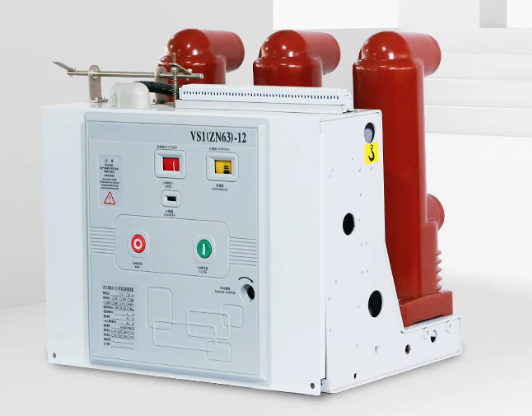
Selecting the right vacuum circuit breakers for transformer protection is a critical engineering decision that directly impacts system reliability, safety, and operational longevity. Transformers represent substantial capital investments, and their protection against electrical faults requires precision and technical understanding. Many engineers approach this specification process without a clear methodology, leading to undersized breakers, incompatible relay settings, or misaligned transformer protection strategies that compromise overall system performance.
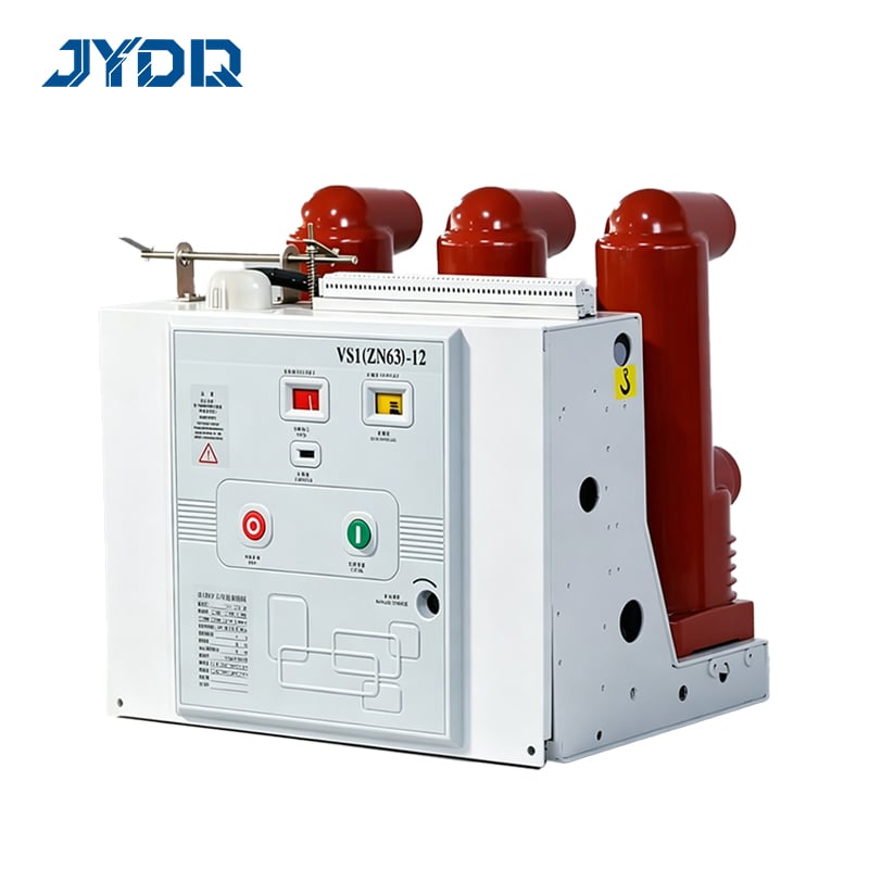
Vacuum circuit breakers have become the preferred solution for medium-voltage transformer protection due to their superior arc-quenching capability, minimal maintenance requirements, and environmental benefits. Unlike oil-filled or SF6 breakers, vacuum interruption technology delivers consistent breaking performance across a wider range of fault conditions while eliminating toxic fluid disposal concerns. This guide walks through the essential specification process, covering load calculations, fault analysis, breaker rating selection, and relay coordination to ensure your transformer protection system meets industry standards and operational demands.
Understanding Transformer Protection Requirements and Breaker Selection Fundamentals
Core Protection Principles for Transformer Systems
Transformer protection involves defending against multiple fault scenarios, including internal faults, external circuit faults, and overload conditions. The vacuum circuit breaker serves as the primary disconnect device and fault interruption mechanism, working alongside protective relays to sense abnormal conditions and trigger breaker operation. The breaker rating must accommodate the transformer's full-load current while providing adequate fault-clearing capability. Understanding these requirements begins with gathering transformer nameplate data: primary and secondary voltage ratings, MVA capacity, impedance, cooling type, and manufacturer specifications.
The primary function of vacuum circuit breakers in transformer protection is rapid fault isolation before damage escalates. A breaker rated too low will nuisance trip during normal inrush currents that naturally occur when energizing transformers. A breaker rated too high may fail to interrupt faults within safe time limits, allowing transformer damage or secondary faults downstream. This balance requires careful analysis of both steady-state operating conditions and dynamic transient behavior during switching and fault events.
Calculating Required Breaker Specifications
Begin by determining the transformer's primary-side full-load current using the standard formula: FLC equals MVA rating multiplied by 1000, then divided by the primary voltage in kilovolts, and finally divided by 1.732 for three-phase systems. This calculation establishes the minimum continuous current rating the vacuum circuit breaker must handle without thermal stress. For a 10 MVA, 69 kV to 13.8 kV transformer, the primary-side FLC is approximately 84 amperes. The selected breaker rating should be the standard size equal to or slightly above this calculated value.
Next, establish the breaker's short-circuit interrupting rating based on the transformer's location within the power system. This requires determining the three-phase fault current at the breaker location, which depends on system fault level, transformer impedance, and upstream protection coordination. The vacuum circuit breaker's interrupting rating must exceed this calculated fault current. For example, if system analysis reveals a 15 kA three-phase fault at the transformer primary, the breaker must have a 15 kA or higher interrupting capacity. This calculation ensures the breaker can safely interrupt faults without arc sustainment or mechanical failure.
Relay Coordination and Protective Scheme Integration
Selecting and Tuning Protective Relays
Modern transformer protection relies on coordinated relay function with vacuum circuit breakers to achieve selective, time-delayed protection that isolates only the faulted element. The relay serves as the 'brain' of the protection system, continuously monitoring current and voltage to detect abnormal conditions. Common relay functions include overcurrent, differential, and thermal overload protection. The relay must be selected based on transformer size, system voltage class, and the protection philosophy adopted—either standalone microprocessor relays or integrated multifunction protection units.
The relay setting process directly impacts the breaker's effectiveness. Overcurrent elements must be calibrated to allow inrush current during normal energization while responding quickly to sustained fault currents. Inrush current typically peaks at five to ten times the full-load current during the first cycle of transformer excitation but decays rapidly within 100 to 200 milliseconds. The relay's instantaneous overcurrent threshold must be set above this inrush peak to prevent false trips, while time-delayed elements catch prolonged overload or persistent fault conditions. This coordination between relay function and vacuum circuit breaker response ensures selective protection across the entire power system hierarchy.
Time-Current Coordination Analysis
Effective transformer protection requires that your relay and breaker combination clear faults faster than upstream devices while remaining slower than downstream protection. This cascading time coordination prevents unnecessary disconnection of healthy circuit sections and directs fault interruption to the specific failed component. Create a time-current coordination curve that plots the relay's operating characteristics against typical fault scenarios. The curve establishes minimum and maximum clearing times for various fault magnitudes, ensuring the vacuum circuit breaker interrupts within acceptable transformer thermal limits.
Transformer thermal capacity governs the maximum allowable fault duration. Transformers typically tolerate faults lasting 2 to 5 seconds without permanent winding damage, depending on insulation class and cooling capability. Your protective relay must be calibrated to clear faults well before these thermal limits are exceeded. If system fault levels are extremely high, the vacuum circuit breaker may operate within its first mechanical cycle, providing nearly instantaneous protection. Conversely, in lower-fault systems, the relay's time-delayed elements manage the clearing sequence, allowing coordination with other protective devices.
Practical Implementation and Specification Best Practices
Conducting Load Flow and Fault Analysis
Before finalizing vacuum circuit breaker selection, conduct comprehensive load flow and short-circuit analysis using industry-standard power system software. Load flow analysis reveals the transformer's expected steady-state current under normal operation and identifies seasonal or operational variations that affect breaker duty. Short-circuit analysis calculates fault currents throughout the system under various contingency scenarios, establishing the design basis for breaker interrupting rating. These studies provide the technical foundation for all subsequent breaker and relay decisions.
Site-specific factors significantly influence specification decisions. Transformer location within the network, proximity to generation sources, cable routing, and system grounding practices all affect fault current magnitude. A transformer located near a large synchronous generator experiences much higher fault currents than one located on a weak radial distribution feeder. Similarly, system grounding practices—solidly grounded, impedance-grounded, or resonant-grounded—alter both the magnitude and character of fault currents. These factors must be accounted for when selecting the breaker's voltage class, current rating, and interrupting capacity.
Standards Compliance and Equipment Verification
Specify vacuum circuit breakers according to relevant industry standards including IEEE C37.04 for rated current and interrupting capability classification, and IEEE C37.06 for preferred voltage ratings. These standards ensure equipment interoperability and establish consistent performance expectations. The transformer protection scheme must comply with IEEE C37.91, which provides application guidance for protective relays used with transformers. Additionally, verify that selected equipment carries appropriate certifications and has been tested under the specific fault conditions expected at your installation site.
Documentation and testing represent the final specification steps. Prepare detailed one-line diagrams showing the vacuum circuit breaker location, voltage class, current rating, and interrupting capacity. Include relay settings documentation with specific pickup currents, time multipliers, and instantaneous thresholds. Before placing the system in service, conduct factory acceptance tests on the vacuum circuit breaker to confirm mechanical operation and electrical performance. Site acceptance testing should verify relay response and timing at the installation location, confirming that the complete protection system operates as designed.
FAQ
What breaker rating should I specify for a 25 MVA transformer at 138 kV?
For a 25 MVA transformer at 138 kV primary voltage, the full-load current is approximately 105 amperes. You would typically specify a vacuum circuit breaker with 120 or 150 ampere continuous current rating, depending on available standard sizes and system duty expectations. The breaker rating must also meet the transformer protection relay's maximum pickup setting while remaining below the breaker's thermal limit during normal full-load operation.
How does the relay coordinate with the vacuum circuit breaker during a fault?
During a fault event, the protective relay continuously monitors current transformers connected to the transformer primary. When fault current exceeds the relay's pickup threshold, the relay initiates a timing sequence based on its programmed characteristics. Upon timer expiration, the relay sends a trip signal to the vacuum circuit breaker's electromagnetic trip coil, which mechanically opens the breaker contacts and extinguishes the arc in vacuum. This relay-breaker coordination ensures selective, time-delayed response that isolates only the faulted component.
Can I use the same breaker specification for all transformer sizes in my system?
No, each transformer requires a dedicated breaker specification based on its individual nameplate ratings, system location, and fault environment. Using an oversized breaker on a smaller transformer compromises inrush current sensitivity and may prevent proper transformer protection. Conversely, specifying an undersized breaker creates unnecessary nuisance trips and operational instability. Each transformer warrants a thorough calculation and specification process tailored to its unique electrical characteristics and system role.

 EN