When engineers receive technical drawings for a dry type transformer, a systematic review process is essential before installation or procurement decisions are made. The technical drawing serves as the critical bridge between design intent and field implementation, making thorough verification non-negotiable. Engineers must understand that incomplete or misinterpreted drawing information can lead to installation delays, safety risks, and operational inefficiencies. A comprehensive checklist approach ensures no detail is overlooked during this validation phase.
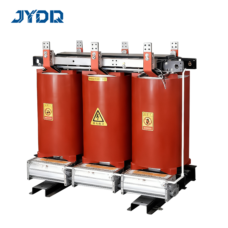
The technical drawing of a dry type transformer contains multiple layers of information that directly impact installation success, operational performance, and long-term reliability. Engineers who develop a disciplined review methodology protect themselves against specification mismatches, safety violations, and costly rework. This article outlines the essential verification steps that professionals should follow when examining dry type transformer technical drawings in industrial and commercial applications.
Verifying Physical Dimensions and Space Requirements
Overall Unit Measurements
The technical drawing must clearly specify the overall height, width, and depth of the dry type transformer unit. Engineers should compare these dimensions against the available installation space in the electrical room or vault to confirm adequate clearance on all sides. The drawing should indicate whether the unit has a standard footprint or custom dimensions based on specific project requirements. Height is particularly critical because overhead clearance directly affects maintenance access, component replacement, and ventilation flow patterns.
Weight Distribution and Foundation Load
Technical drawings for a dry type transformer must include total unit weight and, ideally, a load distribution diagram showing concentrated loads at bearing points. Engineers need to verify that the floor or support structure can accommodate these loads without deflection or reinforcement concerns. The drawing should specify whether vibration isolation pads are required and their placement coordinates. Mounting bolt patterns and torque specifications must be clearly visible so installation teams follow correct assembly procedures.
Evaluating Connection Points and Electrical Specifications
Primary and Secondary Winding Connection Details
The technical drawing must provide precise connection diagrams showing primary voltage class, secondary voltage class, and vector group information for the dry type transformer. Engineers must verify that the connection configuration matches system requirements—whether delta, wye, or delta-wye arrangements are correct for the application. Transformer terminal locations, labeling conventions, and insulation levels should be explicitly marked on the drawing. Any phase rotation or polarity markings must be clearly identified to prevent incorrect installation and operational failures.
Terminal Box Configuration and Cable Entry
Detailed dimensions of the terminal box, cable entry points, and ground connection locations are fundamental details on the technical drawing. Engineers should confirm that cable entrance sizing accommodates the specified conductor sizes for both high and low voltage sides. The drawing should show cable lug specifications, torque requirements for terminal connections, and any environmental sealing recommendations. Connection diagrams must indicate grounding electrode attachment points and the resistance specification for grounding conductors.
Assessing Cooling System and Environmental Performance Requirements
Ventilation and Heat Dissipation Pathways
For a dry type transformer, the technical drawing must clearly show air intake and exhaust locations to ensure proper ventilation and heat dissipation capability. Engineers need to verify that surrounding equipment or wall placement does not obstruct cooling airflow paths. The drawing should specify minimum clearances around ventilation openings and identify whether additional ductwork or fans are required based on ambient temperature conditions. Thermal characteristics, including rated temperature rise and continuous load capacity, must be documented on the drawing for compliance verification.
Enclosure Rating and Environmental Protection
The technical drawing must specify the IP rating (ingress protection) or NEMA enclosure classification appropriate for the installation environment. Engineers should confirm that the dry type transformer enclosure rating matches exposure to dust, moisture, or corrosive conditions at the proposed location. Dimensions of any protective barriers, cable trays, or mounting brackets should be included to help engineers plan the complete installation footprint. The drawing should also indicate transformer nameplate location, access requirements for cooling components, and maintenance clearance zones.
FAQ
What critical dimensions should engineers never skip on a dry type transformer technical drawing?
Engineers must verify overall footprint dimensions, height clearance, mounting bolt pattern, connection terminal spacing, and ventilation opening sizes. These dimensions directly impact installation feasibility and operational safety, making them the highest-priority checks before procurement or site preparation.
How do engineers verify correct connection details on the technical drawing?
Review the voltage class ratings, vector group, winding configuration (delta or wye), terminal labeling, and phase rotation indicators. Compare these details against system single-line diagrams and electrical specifications to ensure the dry type transformer matches the intended application and prevents phase-sequence errors.
Why are cooling system specifications important in the technical drawing review?
Cooling system specifications determine whether the dry type transformer can dissipate design loads in the planned environment without exceeding temperature limits. Insufficient ventilation clearance or obstructed airflow can cause overheating, reduce transformer life, and trigger protection shutdowns during normal operation.

 EN