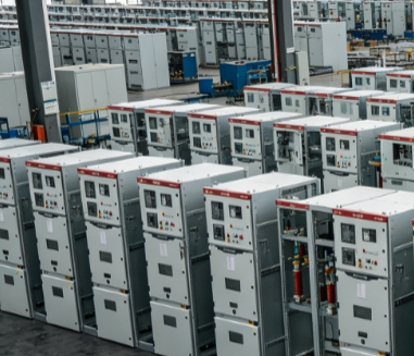
Planning feeder circuits in a low voltage distribution panel requires strategic thinking about load distribution, circuit protection, and operational safety. A low voltage distribution panel serves as the central hub where electrical power is divided and managed across multiple circuits, each designed to serve specific equipment or zones within an industrial facility. Proper feeder circuit planning ensures reliable operation, minimizes downtime, and supports future system expansion.
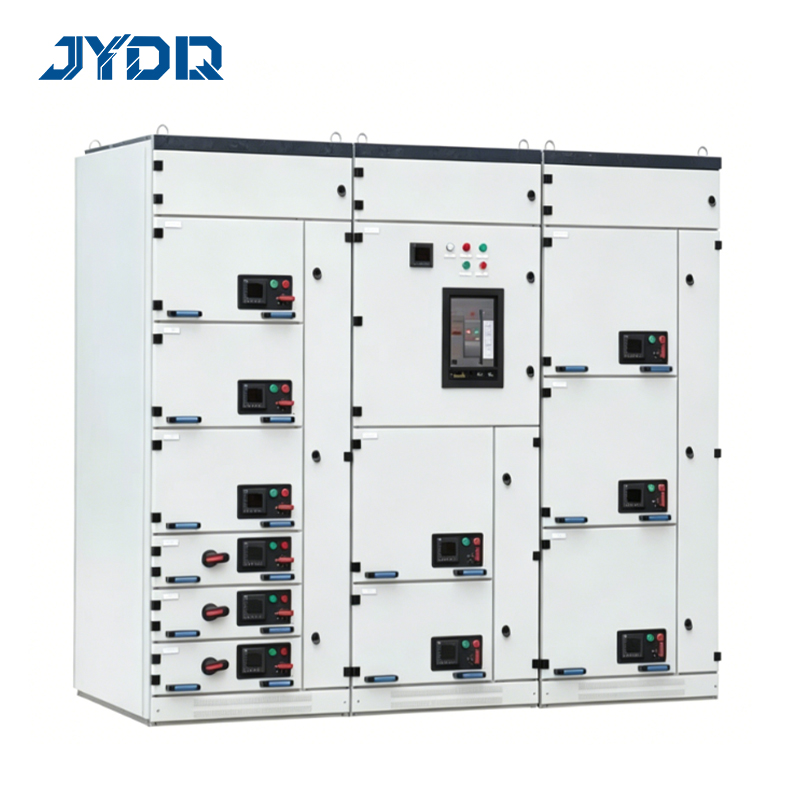
The foundation of effective feeder circuit planning lies in understanding how power flows through your LV panel and how each circuit contributes to overall system performance. When you design feeder circuits systematically, you create a balanced electrical infrastructure that protects equipment, optimizes energy use, and simplifies maintenance activities. This approach transforms your low voltage distribution panel from a simple junction point into an intelligent distribution system aligned with production demands.
Understanding Feeder Circuit Fundamentals
Core Principles of Circuit Distribution
Feeder circuit design begins with calculating total connected load and understanding how that load distributes across your facility. Each feeder circuit acts as a dedicated pathway from the main panel to a specific area or piece of equipment, carrying its own protection devices and monitoring systems. The LV panel must accommodate these feeder circuits while maintaining proper clearances, thermal management, and accessibility for maintenance staff.
Load diversity is essential when planning feeder circuits within your low voltage distribution panel. Not all equipment operates simultaneously at full capacity, so engineers apply diversity factors to calculate the actual demand rather than the theoretical maximum. This calculation determines the size of conductors, the rating of protective devices, and the overall capacity of your distribution infrastructure.
Circuit Protection and Isolation
Every feeder circuit must include appropriate protective devices, typically circuit breakers or fuses, sized according to the circuit's amperage rating and the connected load. These devices protect against overloads and short circuits, preventing damage to downstream equipment and ensuring operator safety. Isolation capability is equally important—each feeder circuit should be independently switchable, allowing technicians to work on one circuit without de-energizing the entire LV panel or facility.
Strategic Planning for Feeder Circuit Layout
Load Analysis and Categorization
Begin feeder circuit planning by conducting a comprehensive load audit across all equipment and processes within your facility. Categorize loads into continuous loads, intermittent loads, and emergency loads, as each category requires different approaches within the low voltage distribution panel. Continuous loads such as compressors or chillers demand stable circuit allocation, while intermittent loads like production machinery may share circuits based on operational schedules.
Future growth capacity must be built into your feeder circuit distribution plan from the outset. Reserve 20 to 30 percent of available space and capacity in your LV panel for future equipment additions and process expansions. This forward-looking approach prevents costly panel upgrades and allows your distribution system to scale alongside your business demands.
Spatial Organization Within the Panel
Physical layout of feeder circuits within your low voltage distribution panel affects maintenance accessibility, thermal performance, and troubleshooting efficiency. Organize circuits logically by department, process line, or equipment function so technicians can quickly locate specific circuits during emergency situations. Group related circuits together and maintain clear labeling on both the panel face and internal wiring diagrams.
Thermal management within an LV panel directly impacts the longevity and reliability of protective devices and bus bars. Position high-load feeders and distribution equipment to allow proper air circulation, preventing hotspots that could degrade insulation or trigger nuisance trips. Many industrial facilities install forced-air cooling or thermal monitoring when feeder circuits approach the panel's thermal limits.
Implementation and Best Practices for Distribution
Conductor Sizing and Cable Selection
Proper conductor sizing is fundamental to safe feeder circuit operation within any low voltage distribution panel. Use the national electrical code tables and your local authority having jurisdiction guidelines to select conductors based on calculated load, circuit length, and ambient temperature conditions. Undersized conductors create excessive voltage drop and heat, while oversized conductors waste copper material and increase project costs unnecessarily.
Select cable types based on your facility's environment and installation method when routing feeders from the LV panel to end-use equipment. Indoor panels typically use THHN or similar insulation, while outdoor or harsh-environment applications require armored cable or conduit protection. Each feeder circuit cable should be clearly color-coded and numbered to match panel labeling and circuit documentation.
Documentation and Maintenance Protocols
Comprehensive documentation transforms your low voltage distribution panel planning from a one-time design exercise into an ongoing operational asset. Create detailed one-line diagrams showing feeder circuits, protection ratings, load destinations, and distribution pathways. Maintain updated equipment schedules listing all connected loads, their nameplate ratings, and operational characteristics.
Establish routine inspection schedules for the LV panel and all feeder circuits to identify developing issues before they cause equipment failure. Check for loose connections, discoloration indicating heat damage, and corrosion on bus bars or terminals. Train facility personnel to recognize warning signs like unusual sounds, burning odors, or erratic circuit breaker operation, responding quickly to prevent escalation.
FAQ
What determines the number of feeder circuits I need in my low voltage distribution panel?
The number of feeder circuits depends on your total facility load, equipment distribution across departments or zones, and desired circuit protection granularity. Most industrial facilities use one primary feeder circuit per significant load area or process line, with additional circuits for backup equipment and future expansion. Your electrical engineer will calculate specific requirements based on load analysis and facility layout, ensuring your LV panel provides adequate distribution capacity.
How should I balance loads across feeder circuits within a low voltage distribution panel?
Load balancing across feeder circuits prevents equipment overheating and extends the lifespan of protective devices. Distribute connected loads as evenly as possible across all available circuits, accounting for diversity factors and duty cycles of specific equipment. If certain circuits consistently handle higher loads, consider upgrading their protective device ratings or redistributing loads to underutilized circuits in future expansion phases.
Can feeder circuits be modified after a low voltage distribution panel is installed?
Modifying feeder circuits after installation is possible but requires careful planning and often involves downtime. Adding new circuits may require panel upgrades if available capacity is exhausted, and changing circuit destinations demands rewiring and retesting. Design your initial feeder circuit plan with adequate reserve capacity to accommodate modifications without expensive panel replacement or temporary service interruptions.

 EN