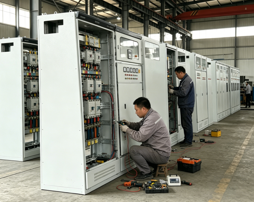
A vacuum circuit breaker is a critical component in electrical distribution systems that requires thorough inspection before commissioning to ensure safe and reliable operation. Proper VCB inspection prevents equipment failures, protects personnel, and safeguards assets from electrical hazards. Understanding the inspection process is essential for electrical engineers, maintenance teams, and facility managers responsible for bringing new switchgear installations online.
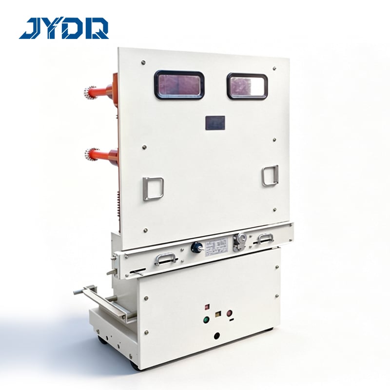
Before commissioning begins, systematic inspection ensures that all vacuum circuit breaker components meet design specifications and industry standards. This process identifies manufacturing defects, shipping damage, and installation issues that could compromise performance. Proper commissioning procedures extend equipment lifespan and establish a baseline for future maintenance scheduling and predictive diagnostics.
Visual and Mechanical Inspection
Exterior Component Assessment
Begin your vacuum circuit breaker inspection by carefully examining the external housing, insulating materials, and structural framework. Look for cracks, discoloration, or signs of moisture penetration in the porcelain or epoxy resin exterior. Check that all mounting bolts, connection terminals, and mechanical linkages are secure and free from corrosion or damage during transit. Inspect the operating handle and manual trip mechanism to confirm smooth mechanical movement without resistance or grinding sounds.
Verify that nameplate information matches your installation documentation, including voltage ratings, current capacity, and trip settings. Examine cable termination points for proper alignment and verify that all conductor connections use specified torque values according to manufacturer guidelines. Document any physical damage or discrepancies in detailed inspection records before proceeding with electrical testing.
Internal Vacuum Chamber Inspection
The internal vacuum chamber represents the core functional element of your vacuum circuit breaker and requires specialized inspection. Visual inspection through viewing ports or transparent windows should reveal a clean, dust-free interior without visible contact erosion or metallic particles. Any cloudiness, discoloration, or residue inside the chamber indicates potential vacuum degradation or contamination requiring further investigation or replacement before commissioning proceeds.
Measure vacuum level using calibrated vacuum gauges and diagnostic equipment specified by the manufacturer. Typical vacuum levels range from 0.1 to 0.6 torr, with variations depending on VCB design and rated interrupting capacity. Document vacuum readings at multiple chamber locations to identify any pressure gradients that might indicate seal leakage or manufacturing defects.
Electrical Testing and Verification
Insulation Resistance Measurement
Conduct insulation resistance testing using high-voltage megohmeters calibrated to the vacuum circuit breaker voltage class. Measure resistance between primary conductors and ground, between phase-to-phase conductors, and between moving and stationary contacts. Acceptable insulation resistance typically exceeds 100 megohms for medium-voltage VCBs, with specific thresholds defined in IEEE and IEC standards applicable to your equipment rating. Record baseline measurements for comparison during future commissioning events and maintenance cycles.
Test insulation resistance after applying one-minute dwell time to allow capacitive charging to stabilize. Compare results against manufacturer specifications and industry benchmarks to identify potential weaknesses before energization. Low resistance readings demand investigation of moisture ingress, dust contamination, or manufacturing defects before proceeding with commissioning activities.
Contact Resistance and Current Path Verification
Measure contact resistance across main power contacts using specialized low-resistance ohmmeters with milliohm accuracy. Contact resistance should remain stable within specified limits, typically below 0.5 milliohms for new vacuum circuit breaker installations. Unequal resistance between phases indicates asymmetrical contact wear, misalignment, or defects requiring mechanical adjustment or component replacement.
Verify continuity through all auxiliary contacts, including alarm switches, position indicators, and protective relay coils. Inspect relay coil operation through applied voltage testing and confirm proper pick-up and drop-off characteristics match control specifications. Test manual closing and tripping operations to verify mechanical and electrical coordination during normal and emergency scenarios.
Operational Performance During Commissioning
No-Load Operating Tests
Perform manual opening and closing cycles without load current to verify mechanical operation and contact travel distances before commissioning under energized conditions. Execute minimum five complete operating cycles, observing smooth handle movement, audible contact engagement, and proper mechanical locking in open and closed positions. Measure contact opening time using oscilloscopes or specialized timing equipment to confirm performance within 20-50 millisecond range typical for vacuum circuit breaker designs.
Record operating coil voltages during motorized closing operations, confirming that closing coil currents drop to acceptable holding levels after contact engagement. Document any mechanical friction, noise, or irregular operation for investigation before proceeding to load testing stages during commissioning protocols.
Commissioning Under Load Conditions
Gradually energize the vacuum circuit breaker at reduced voltage levels, monitoring for abnormal sounds, vibration, or thermal effects during initial energization. Measure primary and secondary current flows through protection relays and instrument transformers, confirming proper metering accuracy and protective function operation. Progressively increase load current in incremental steps while monitoring contact temperatures using thermal imaging equipment to establish safe operating baselines for future reference.
Execute final commissioning tests including protective relay coordination verification, automatic reclosing function testing if applicable, and synchronization checks in multi-breaker configurations. Confirm that VCB tripping occurs at designed pickup levels and that operating times meet protection coordination requirements with upstream and downstream protective devices in your electrical network.
FAQ
What are the critical acceptance criteria for vacuum circuit breaker inspection before commissioning?
Critical acceptance criteria include insulation resistance measurements exceeding 100 megohms, vacuum level between 0.1-0.6 torr, contact resistance below 0.5 milliohms, and operating times within 20-50 milliseconds. All mechanical components must function smoothly, nameplate information must match documentation, and protective functions must coordinate properly with system protection schemes. Visual inspection should reveal no visible damage, moisture, or contamination inside the vacuum chamber.
How often should vacuum circuit breaker inspection occur during commissioning projects?
Comprehensive inspection should occur at three critical stages during commissioning: upon delivery before installation, after mechanical installation and electrical connections are completed, and during final functional testing under load conditions. This staged approach identifies manufacturing defects early, catches installation errors before energization, and confirms equipment readiness before transition to operational service. Additional spot inspections may be warranted after extreme environmental exposure or extended storage periods.
What documentation should be maintained from vacuum circuit breaker inspection and commissioning activities?
Maintain detailed records including nameplate photographs, insulation resistance measurements, vacuum level readings, contact resistance data, operating time measurements, thermal imaging results, and protective relay coordination documentation. Document any defects discovered, corrective actions taken, and equipment modifications made during commissioning. Retain baseline measurements as reference data for future maintenance decisions, predictive diagnostics, and troubleshooting of potential equipment degradation over operational life.

 EN