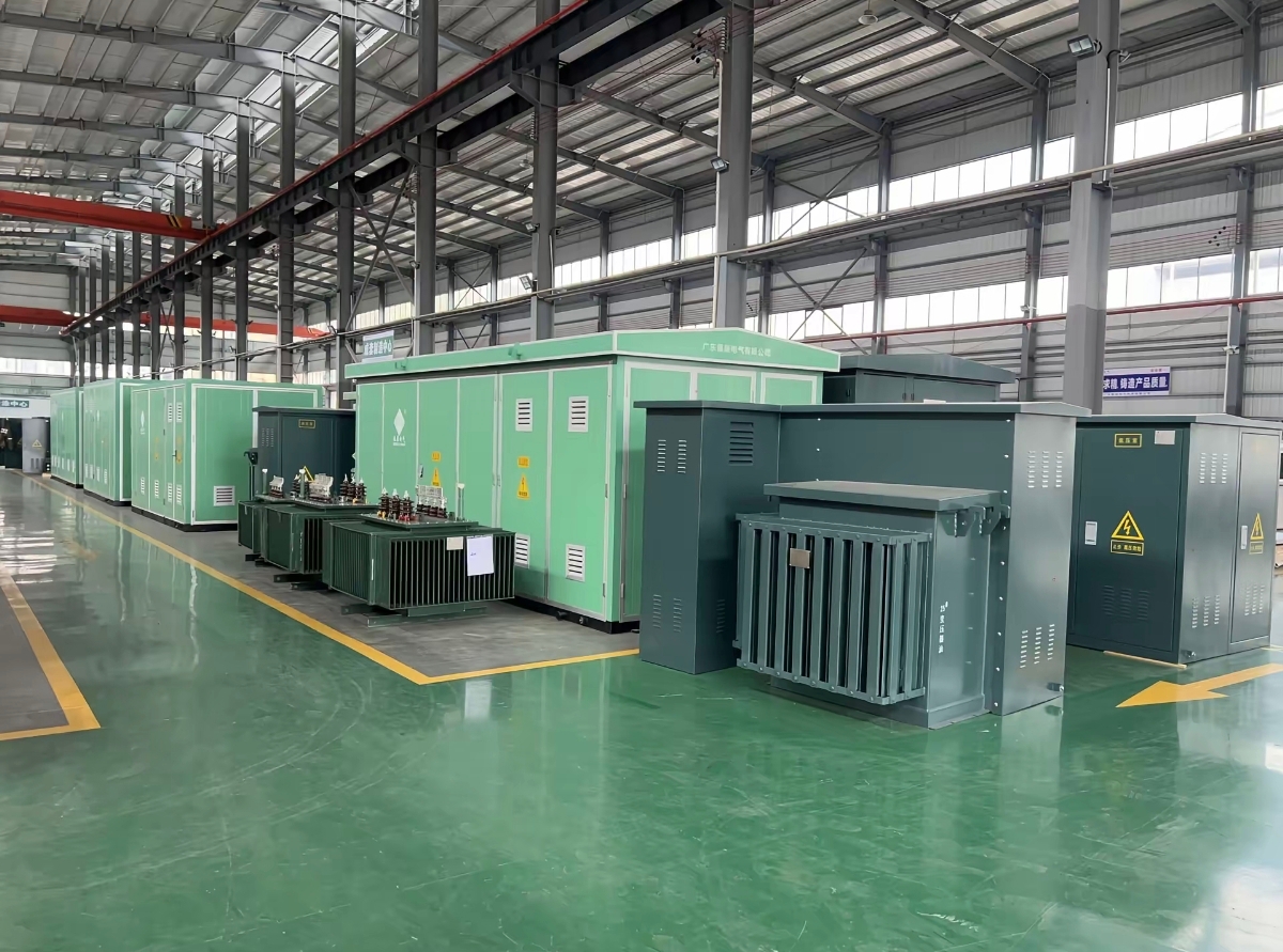
Integrating a transformer with medium-voltage switchgear is a critical engineering task that determines the reliability, safety, and efficiency of electrical substations. The proper integration of these components ensures optimal power distribution, minimizes downtime, and protects equipment from electrical faults. Whether you're designing a new substation or upgrading an existing facility, understanding the fundamentals of transformer integration with medium voltage systems is essential for maintaining compliance with industry standards and achieving long-term operational success.
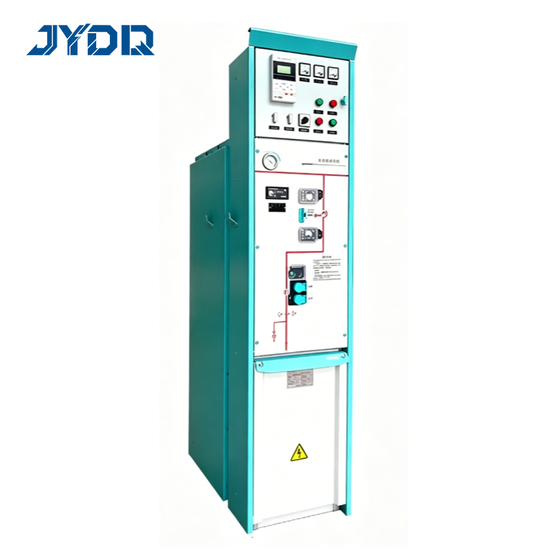
The integration process involves careful coordination between transformer specifications, switchgear configuration, and substation layout. Successful switchgear integration requires knowledge of electrical compatibility, mechanical alignment, and operational protocols. This comprehensive guide walks you through the essential steps, technical considerations, and practical strategies needed to integrate transformers effectively within your medium voltage infrastructure.
Understanding Transformer and Switchgear Fundamentals
Core Components and Their Roles
A transformer serves as the backbone of power conversion in electrical systems, stepping voltage up or down to appropriate levels for distribution and consumption. Medium-voltage switchgear acts as the control and protection interface, managing current flow and isolating equipment during maintenance or fault conditions. Together, they form a unified system where the transformer converts power while the switchgear ensures safe, controlled operation. Understanding how each component functions independently helps you appreciate why their integration must be precise and well-engineered.
Electrical and Mechanical Compatibility
Before beginning switchgear integration, verify that transformer ratings match the medium voltage system requirements. Check voltage levels, frequency, impedance values, and cooling methods to ensure compatibility. Mechanical considerations include mounting arrangements, clearance distances, and vibration isolation. The transformer's weight and dimensions must fit within the substation layout, and switchgear must be positioned to allow safe access for maintenance. These compatibility checks prevent costly rework and operational failures after installation.
Key Integration Principles for Medium-Voltage Systems
Connection Design and Busbar Configuration
The electrical connection between transformer and medium voltage switchgear requires careful design of busbars, cables, and protection devices. High-current paths must be minimized to reduce losses and heat generation. Busbar sizing depends on the transformer's power rating and expected current levels. When integrating switchgear, ensure that busbars can handle peak currents without excessive voltage drop. Use appropriately rated disconnects and surge protection devices to safeguard against transient overvoltages. Proper grounding connections are mandatory for both safety and equipment protection in substation designs.
Protection and Coordination Strategy
Effective switchgear integration includes layered protection schemes that prevent cascading failures across the substation. Install overcurrent relays, differential protection, and ground-fault detection coordinated with the transformer's characteristics. These protective devices must operate selectively, isolating only the faulted section while keeping the rest of the system operational. The medium voltage side requires separate protection settings from the low-voltage side. Coordination curves must be calculated and tested to ensure that protection devices respond correctly to each type of fault, protecting both the transformer and connected equipment.
Implementation and Operational Best Practices
Installation and Commissioning Steps
Begin installation by confirming the substation foundation meets transformer and switchgear load requirements. Position the medium voltage switchgear to minimize cable runs and simplify maintenance access. Connect the transformer primary windings to the switchgear output terminals using appropriately sized, insulated conductors. Install all protection devices, control wiring, and monitoring systems before energizing. Commissioning includes voltage tests, insulation resistance measurements, and operational checks under load. Test switchgear operation under simulated fault conditions to verify protection response. Document all settings, test results, and as-built configurations for future reference and troubleshooting.
Ongoing Monitoring and Maintenance
After successful integration, establish regular monitoring and maintenance protocols for the combined system. Track transformer temperature, load levels, and switchgear operational status through SCADA or local monitoring systems. Perform infrared thermography on connections to detect hot spots indicating poor contact or loose terminations. Schedule preventive maintenance aligned with the manufacturer's recommendations for both the transformer and switchgear. Test protection devices periodically to confirm they remain calibrated and responsive. Maintain detailed maintenance records and load profiles to identify trends and plan upgrades before capacity or reliability becomes compromised. This proactive approach maximizes substation uptime and extends equipment lifespan.
FAQ
What are the critical voltage and impedance values to verify during transformer switchgear integration?
Before integrating a transformer with medium voltage switchgear, confirm that primary and secondary voltage ratings align with your system requirements. Verify the transformer's impedance percentage, which affects fault current levels and must match the protection coordination calculations. Check the frequency rating, cooling method, and tap changer range if present. These electrical parameters directly influence how the switchgear protection devices are calibrated and how the transformer behaves during overload or fault conditions. Mismatched specifications can result in inadequate protection or equipment damage.
How does switchgear integration affect substation grounding and earthing design?
Proper grounding is fundamental to safe switchgear integration and medium voltage system stability. The transformer neutral and all metal structures must connect to the main earth grid with low-resistance paths. Grounding cables must be sized according to fault current magnitudes and must reach from the transformer, through the switchgear frame, to the substation ground electrode. Poor grounding can result in dangerous voltage rises during faults and impaired protection device operation. Regularly measure ground resistance and verify continuity of all grounding connections as part of routine substation maintenance.
What safety precautions should be taken during and after transformer switchgear integration?
Follow lockout-tagout procedures before working on any part of the integrated system. Verify de-energization with appropriate test equipment and ensure all stored energy is safely discharged. Wear personal protective equipment rated for the medium voltage levels present. After integration is complete, post hazard warning labels indicating live circuit locations and voltage levels. Ensure that only trained personnel operate switchgear and that emergency procedures are documented and practiced. Conduct a final safety audit before placing the substation into service to identify any potential hazards or compliance gaps.

 EN