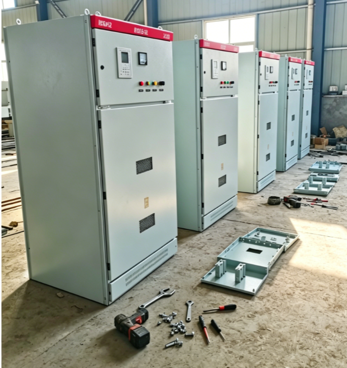
Planning cable connections for high voltage switchgear requires careful engineering and systematic approach to ensure safety, reliability, and operational efficiency. The cable termination process represents one of the most critical phases in electrical system installation, where improper planning can lead to equipment failure, safety hazards, and costly downtime. Understanding the principles of proper cable layout and connection methodology is essential for electrical engineers, technicians, and facility managers involved in power distribution systems.
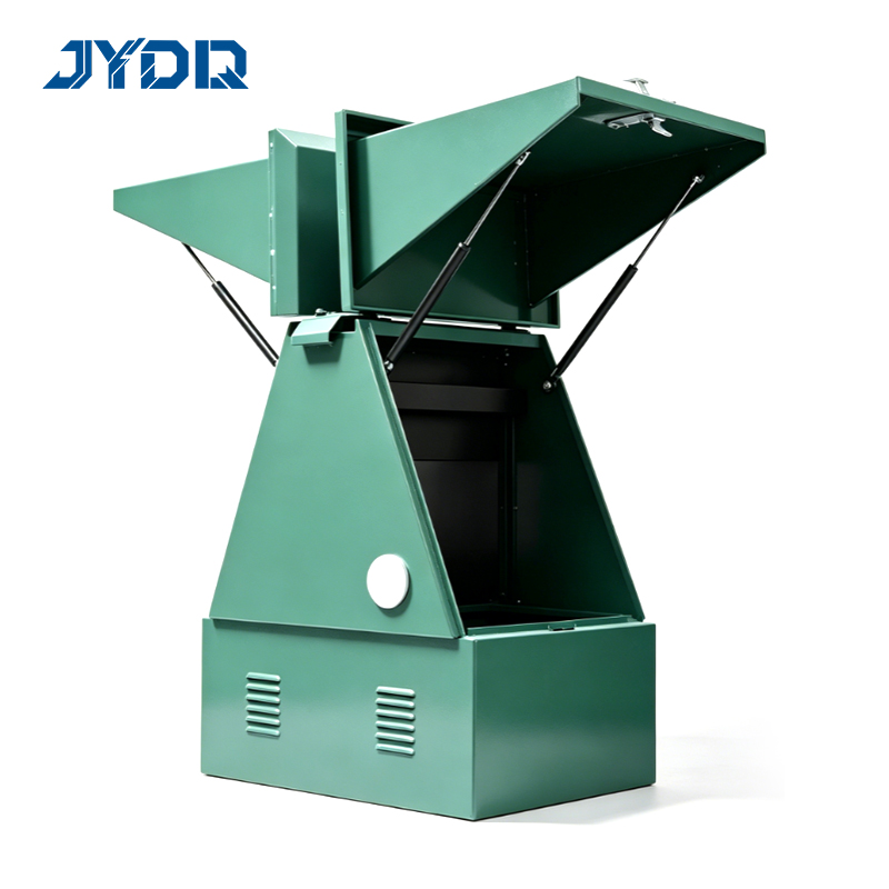
Successful cable connection planning combines technical knowledge with practical field experience. The installation layout must accommodate physical space constraints, thermal management requirements, and accessibility for maintenance while maintaining electrical performance standards. This comprehensive guide explores the essential steps and considerations for developing a robust cable connection strategy that meets industry standards and operational demands.
Understanding High Voltage Switchgear Cable Requirements
Core Principles of Cable Termination
Cable termination in high voltage switchgear installations demands strict adherence to manufacturer specifications and industry codes. Each termination point must provide secure mechanical contact, proper electrical conductivity, and adequate insulation protection. The cable termination process involves selecting appropriate connector types, ensuring correct conductor sizing, and implementing proper sealing against moisture and contaminants. High voltage switchgear systems typically operate at voltages exceeding 1 kV, requiring enhanced insulation and rigorous quality control throughout the termination process.
The selection of termination hardware directly impacts system reliability and safety. Copper or aluminum connectors must match the cable conductor material to prevent galvanic corrosion. Proper torque specifications ensure mechanical stability without damaging conductor strands or creating weak contact points. Termination techniques vary based on cable construction, voltage class, and environmental conditions, requiring detailed planning before installation begins.
Environmental and Space Considerations
Layout planning for high voltage switchgear installations must account for thermal dissipation, vibration isolation, and environmental exposure. Cable routing should minimize electromagnetic interference and maintain adequate clearances from grounding equipment and other metallic structures. The installation environment, whether indoor or outdoor, directly influences cable protection requirements and termination material selection. Corrosive atmospheres, extreme temperatures, and moisture exposure all factor into comprehensive layout design.
Developing Your Cable Connection Layout Strategy
Systematic Planning Approach
Effective installation planning begins with detailed site surveys and comprehensive documentation of existing infrastructure. Engineers must map cable routes, identify junction points, and calculate voltage drop across connection points. The layout should minimize cable lengths where practical while maintaining sufficient slack for thermal expansion and maintenance access. Three-dimensional modeling and computer-aided design tools help visualize complex routing scenarios before physical installation commences.
A systematic approach requires coordination between electrical, civil, and mechanical engineering disciplines. Cable trays, conduit systems, and support structures must be installed before cable termination work begins. The installation schedule should sequence activities to allow proper curing of potting compounds and cooling periods between thermal cycling tests. Detailed drawings must show termination points, cable entry angles, and clearance zones for each connection location.
Coordinating Multiple Systems
Most high voltage switchgear installations involve coordinating power cables, control signal wiring, and grounding connections within shared infrastructure. Cable termination points must be physically separated based on voltage classification and signal type to prevent cross-contamination and interference. The layout must accommodate future expansion without compromising existing connection integrity. Labeling systems and color-coding schemes facilitate identification during maintenance and troubleshooting activities.
Implementation Best Practices for Cable Installation
Pre-Installation Verification
Before beginning cable termination work, all materials must be verified against specifications and inspected for damage. High voltage switchgear connections require specialized tools including cable strippers, crimpers, and temperature monitoring equipment. Environmental conditions during installation significantly affect termination quality, with humidity and temperature constraints specified in technical standards. Proper surface preparation, including conductor cleaning and degreasing, establishes the foundation for reliable long-term performance.
Documentation of material lot numbers, installation dates, and environmental conditions creates essential records for future maintenance and troubleshooting. Each cable termination should be photographed and recorded in the facility database. Quality assurance protocols including hi-pot testing and resistance measurements verify installation integrity before energization. These verification steps prevent latent defects that might manifest as failures during service.
Advanced Termination Techniques
Modern cable termination for high voltage switchgear often employs heat-shrink tubing, compression connectors, and potted terminations depending on system voltage and environmental conditions. Press-on connectors and mechanical lugs offer advantages for field installations where specialized equipment may be limited. Epoxy potting compounds provide superior moisture protection and mechanical strength for demanding applications. Each termination method requires specific installation procedures, tool calibration, and quality verification protocols to ensure compliance with electrical standards.
Cable installation practices must account for thermal cycling effects and long-term material degradation. Proper spacing between adjacent cables ensures adequate cooling and reduces localized heating at termination points. Support structures should distribute load evenly across multiple termination points rather than concentrating stress on individual connections. Regular maintenance protocols including thermal imaging and visual inspections extend service life and prevent unexpected failures.
FAQ
What voltage specifications apply to high voltage switchgear cable termination?
High voltage switchgear systems typically operate at 1 kV to 765 kV, with termination specifications varying significantly across this range. Low voltage switchgear below 1 kV uses standard connectors while medium voltage systems between 1 kV and 35 kV require enhanced insulation and controlled torque procedures. Extra high voltage applications exceeding 230 kV demand specialized termination hardware, extended drying periods for potting compounds, and rigorous quality verification testing. Manufacturer specifications and applicable IEEE or IEC standards define exact requirements for each voltage class.
How should cable layout planning account for future maintenance and expansion?
Effective installation layout reserves space for cable additions, conductor replacement, and maintenance access around existing termination points. Underutilized cable trays and conduit systems should be sized to accommodate anticipated future connections without requiring system modifications. Clear labeling and documentation enable technicians to safely identify connection points during maintenance activities. The layout should minimize disruption to operational circuits when maintenance or upgrades occur, typically by grouping related cables and termination points in accessible areas.
What common mistakes should be avoided during high voltage switchgear cable termination?
Inadequate preparation including insufficient conductor stripping, contamination from moisture or oxidation, and improper tool calibration represents the most frequent cause of termination failures. Over-torquing or under-torquing connectors creates either material damage or insufficient contact pressure. Mixing connector materials or using non-compatible termination hardware leads to corrosion and eventual failure. Failure to follow manufacturer specifications regarding potting compound application, curing time, and environmental conditions compromises long-term reliability and safety of high voltage switchgear installations.

 EN