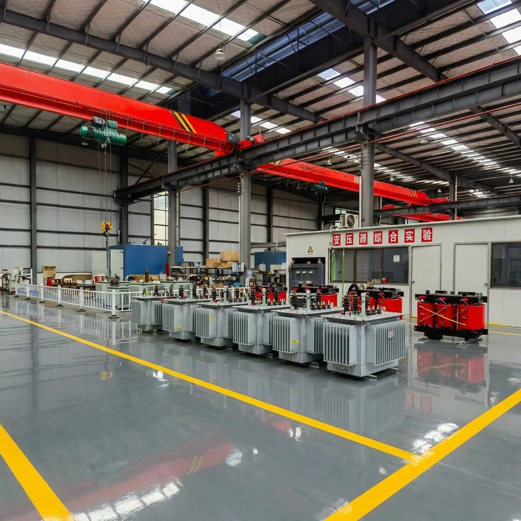
Planning transformer protection for a new substation requires careful consideration of multiple interconnected systems and operational requirements. A transformer is among the most critical and expensive assets in any electrical infrastructure, making its protection not merely a technical necessity but a fundamental business imperative. Effective transformer protection strategy prevents catastrophic failures, minimizes downtime, and ensures continuous power delivery to downstream networks and industrial facilities.
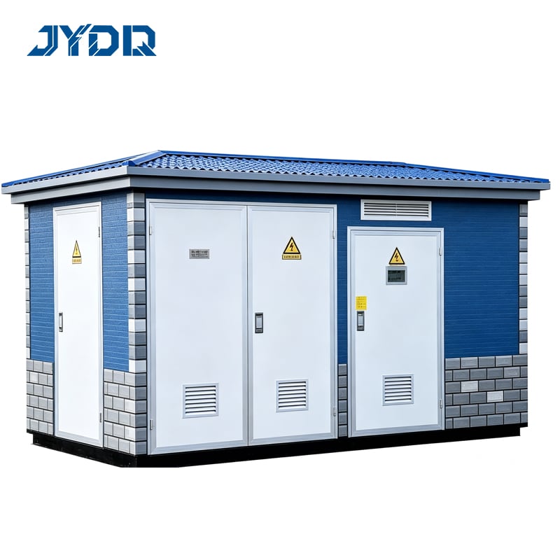
The foundation of any substation design begins with understanding how transformer protection integrates with the broader protection scheme. Modern substations demand a layered defense approach that combines primary and backup protective devices, each serving distinct functions within the overall architecture. This article guides you through the essential planning phases, key protective devices, and decision factors that ensure your substation transformer protection system operates reliably and meets all regulatory compliance requirements.
Understanding Transformer Protection Fundamentals
Core Objectives of Transformer Protection
Transformer protection systems serve three primary objectives: detecting faults, isolating the faulty equipment, and preventing cascading failures across the network. A Transformer protection strategy must address internal winding faults, core damage, overheating conditions, and external short circuits that threaten equipment integrity. Each of these failure modes demands specific detection mechanisms and response protocols embedded within the overall protection philosophy.
The relay serves as the intelligent brain of any transformer protection system, constantly monitoring electrical parameters and making instantaneous decisions about fault conditions. Modern relay technology provides sophisticated algorithms that distinguish between normal transient events and genuine faults, preventing unnecessary nuisance trips that compromise system reliability. This selectivity between legitimate operating conditions and actual faults represents one of the most critical competencies required in modern protection planning.
Regulatory and Operational Context
Transformer protection requirements vary significantly based on voltage classes, capacity ratings, operational context, and applicable regulatory standards. Most jurisdictions mandate specific protection schemes for distribution and power transformers, with stricter requirements applying to larger assets and higher voltage systems. Understanding these regulatory requirements early in the planning phase prevents costly redesigns and ensures your substation meets all compliance obligations from initial commissioning through operational life.
Designing Protection Device Architecture
Primary and Backup Circuit Breaker Configurations
The circuit breaker represents the physical switching device that executes protection decisions made by the relay, interrupting fault currents before they damage the transformer. Planning your substation requires selecting circuit breaker types, ratings, and operating mechanisms that align with your transformer specifications and fault current levels. A properly coordinated circuit breaker must clear faults quickly enough to prevent thermal damage while maintaining sufficient selectivity to isolate only the faulted component rather than disrupting entire system sections.
Most modern substations employ a primary circuit breaker controlled by the main relay, supported by backup protection that activates if the primary device fails to respond. This backup circuit breaker might be located at a higher voltage level or controlled by independent protection logic, ensuring that even in unlikely scenarios where primary protection fails, the transformer receives protection from secondary systems. Calculating fault current values, determining required interrupting ratings, and mapping clearing times between successive protection levels represents essential planning work that must occur before equipment selection begins.
Relay Protection Coordination and Selectivity
A relay operates within a coordinated framework where its response must not only detect faults but also allow upstream devices to operate first when faults occur on downstream equipment. This coordination principle means your relay settings require careful calculation based on fault impedance analysis, conductor sizing, and the protection characteristics of adjacent equipment. Without proper relay coordination, a fault in one section might cause the transformer circuit breaker to trip inappropriately, disconnecting healthy equipment and causing unnecessary service interruptions across multiple customer sections.
Transformer protection relay selection involves choosing between various protection functions such as overcurrent, differential, thermal, and gas detection based on your specific transformer type and substation configuration. Differential protection offers superior selectivity by comparing current flowing into the transformer against current flowing out, immediately identifying internal faults with minimal delay. However, differential protection requires proper current transformer selection and wiring, adding complexity and cost that must be justified through risk assessment against your transformer asset value and service criticality.
Implementation Planning and Commissioning Strategy
Protection Device Coordination Studies
Before finalizing any equipment procurement, comprehensive protection studies must validate that your circuit breaker, relay, and backup protection devices operate in proper sequence during various fault scenarios. These studies involve calculating maximum and minimum fault currents at each device location, then verifying that protection devices clear faults in the intended sequence without unwanted overlap. Protection engineers use specialized software to model these interactions, creating coordination curves that document the time-current relationships between all protective devices in your substation and the surrounding network.
The coordination study process typically identifies margin violations or conflicts where devices might operate incorrectly, requiring iterative adjustments to relay settings or device selections. These adjustments must be validated through the coordination software before equipment purchases, as post-installation changes become increasingly expensive and disruptive. Well-executed coordination studies represent excellent investments in planning that prevent operational surprises and ensure your substation protection performs exactly as intended when actual fault events occur.
Testing, Commissioning, and Operational Readiness
Comprehensive testing protocols must validate that your relay operates correctly across its entire setting range and responds appropriately to various fault conditions. Commissioning tests typically include secondary injection testing of the relay with calibrated current sources, verifying both the protection function accuracy and the circuit breaker trip response. These tests require specialized equipment and expertise, typically performed by qualified technicians under controlled conditions before the substation enters commercial operation.
Post-commissioning planning should include documented maintenance schedules, spare parts identification, and training programs that ensure operations personnel understand the protection system philosophy and respond appropriately during actual incidents. Regular maintenance of circuit breaker mechanisms, contact conditioning, and relay software updates ensures your protection devices remain ready to respond instantaneously when needed. This ongoing operational attention often determines whether protection systems perform reliably throughout their service life or encounter unexpected failures when fault events test their response capability.
FAQ
What are the main causes of transformer failures that protection systems must detect?
Transformer failures originate from winding insulation breakdown due to age or electrical stress, overheating from excessive load or inadequate cooling, short circuits from manufacturing defects or external damage, and moisture ingress that degrades insulation properties. Internal arc faults and partial discharge events signal imminent failure, requiring transformer protection systems to detect these precursor conditions before catastrophic breakdown occurs. Modern protection relies on multiple sensing technologies including dissolved gas analysis, thermal monitoring, and electrical fault detection to capture the diverse failure mechanisms that affect transformer reliability.
How do relay settings differ between distribution and power transformers?
Distribution transformers typically employ simpler protection schemes with standard overcurrent or thermal relay settings, while large power transformers demand sophisticated differential protection with multiple backup layers due to their critical role and high asset value. Distribution transformer protection settings reflect higher acceptable risk levels and simpler fault scenarios, whereas power transformer protection must account for complex network interactions, potential for internal faults with minimal external indication, and catastrophic consequences if protection fails. The relay must be configured and calibrated specifically for each transformer type and application context to optimize the balance between sensitivity and selectivity.
What role does the circuit breaker play in transformer protection execution?
The circuit breaker translates the relay's fault detection decision into physical action by interrupting the fault current and isolating the transformer from the network. Without proper circuit breaker selection and coordination with the relay, even accurate fault detection fails to prevent damage because the breaker must interrupt the fault current before it damages transformer windings. The circuit breaker's interrupting rating, operating mechanism speed, and integration with the relay determine whether protection decisions translate into effective fault isolation or result in delayed response that allows thermal and mechanical damage to occur.

 EN