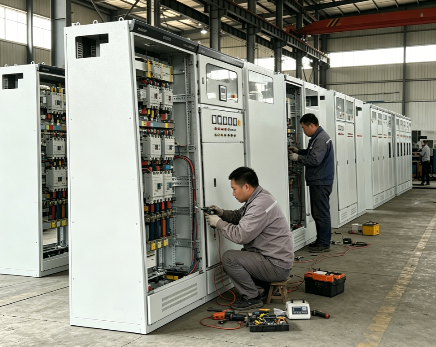
Grounding represents one of the most critical yet often underestimated aspects of any oil immersed transformer installation. When an oil immersed transformer is deployed in industrial facilities, power generation stations, or distribution networks, the quality and design of its grounding system determine whether the equipment will operate safely and reliably. Without proper grounding, an oil immersed transformer becomes vulnerable to electrical faults, equipment damage, personnel injury, and catastrophic system failures that can halt operations and incur substantial costs.
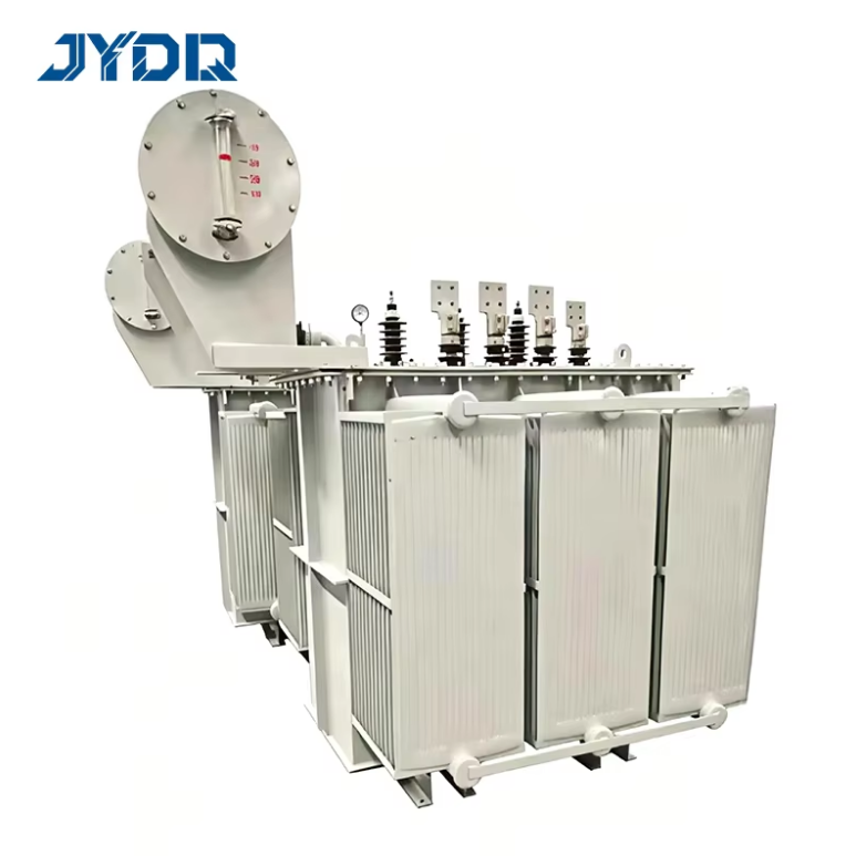
The grounding system for an oil immersed transformer installation serves as the first line of defense against electrical hazards, fault currents, and voltage surges. By establishing a low-impedance path to earth, proper grounding ensures that dangerous voltages dissipate safely into the ground rather than posing a risk to equipment operators or surrounding infrastructure. Understanding why grounding matters and how to implement it correctly is essential for anyone involved in transformer installation, maintenance, or operation.
The Foundation of Electrical Safety Through Grounding
How Grounding Protects Personnel and Equipment
Electrical safety depends fundamentally on creating safe pathways for fault currents. When a phase conductor contacts the transformer frame or the oil tank during normal operation or through insulation failure, grounding provides an immediate pathway for that dangerous current to reach earth potential. This rapid fault detection triggers protective relays and breakers, isolating the fault before personnel contact energized surfaces. Without grounding, such contact scenarios could result in electrocution, severe injuries, or fatal accidents.
An oil immersed transformer installation requires multiple grounding points to achieve comprehensive protection. The transformer tank must be grounded, the neutral point (if accessible) must be grounded, and all metallic structures surrounding the installation must be bonded together and connected to earth. This integrated grounding architecture minimizes voltage differences between accessible surfaces, reducing shock hazards and ensuring that any current flow during a fault event follows the designed grounding path rather than flowing through workers or unintended conductors.
Surge Protection and Voltage Stabilization
Lightning strikes, switching transients, and other electrical disturbances generate voltage surges that can damage transformer windings, insulation, and internal components. A well-designed grounding system works in tandem with surge arresters to clamp these transient overvoltages to safe levels before they propagate into the transformer. The low-impedance earth connection provided by grounding allows surge current to bypass the transformer winding, channeling it safely into the ground. For an oil immersed transformer installation operating in areas with frequent electrical storms or unstable grid conditions, this surge protection capability is invaluable.
Proper grounding also stabilizes the neutral point voltage, preventing neutral shift and harmonic distortion that could degrade transformer performance and lifespan. By maintaining a stable reference to earth potential, the grounding system ensures that phase-to-neutral voltages remain balanced and within acceptable limits, protecting connected loads and reducing stress on insulation systems.
Installation Best Practices for Transformer Grounding
Designing the Grounding System for Installation
Before an oil immersed transformer installation commences, the grounding system design must be engineered based on site-specific conditions, fault levels, and electrical codes. The design process includes soil resistivity testing, fault current calculations, and ground resistance target determination. Most standards require that transformer installations achieve ground resistance values below 1 ohm for large industrial transformers, though specific requirements vary based on voltage levels, fault current magnitude, and local regulations governing electrical safety.
The grounding installation typically involves burying copper or galvanized steel electrodes at strategic locations around the transformer foundation, interconnecting them with conductive cable or busbars, and establishing multiple connection points to the transformer structure. Proper material selection is critical; copper resists corrosion better than steel, extending the service life of the grounding system and maintaining low resistance over decades. The installation must also consider future maintenance access and the need to verify grounding integrity periodically throughout the oil immersed transformer's operating life.
Integration with Transformer and Facility Design
An oil immersed transformer installation often includes concrete pads or plinths that can trap moisture and moisture-rich soil against the grounding electrodes, which improves electrical contact and reduces resistance. However, this moisture can also accelerate corrosion if non-corrosion-resistant materials are used. Proper installation practices include isolating grounding electrodes from corrosive soils, using inspection pits for testing without disturbing the primary grounding installation, and establishing secondary grounding paths through structural steel and cable trays that surround the transformer.
The connection from the transformer tank to the grounding system must use properly sized conductors with mechanical reliability and redundancy. Bolted connections should incorporate star washers or other measures to prevent loosening, and the conductor routing must avoid stress points that could lead to breakage or fatigue. For an oil immersed transformer installation, redundant grounding paths ensure that even if one connection corrodes or fails, backup paths maintain electrical safety.
Compliance, Testing, and Long-Term Reliability
Meeting Electrical Safety Standards and Codes
Transformer installations must comply with standards such as IEEE C62.92, IEC 60071, and national electrical codes that specify grounding requirements for oil immersed transformer facilities. These standards prescribe minimum ground resistance values, testing frequencies, and design criteria that vary based on transformer voltage class and operational environment. Compliance verification requires that the grounding system be installed according to approved designs, tested upon commissioning, and documented thoroughly. The installation contractor bears responsibility for confirming that grounding work meets standard specifications before the oil immersed transformer is energized.
Non-compliance with grounding standards exposes facility operators to liability, equipment damage liability, and regulatory penalties. Insurance requirements for industrial facilities often mandate that transformer installations include certified grounding systems verified by qualified testing professionals, further underscoring the importance of proper installation and documentation practices.
Maintenance and Verification of Grounding Systems
Once an oil immersed transformer installation is operational, ongoing maintenance and periodic testing of the grounding system ensure that resistance remains low and no degradation has occurred. Ground resistance testing should be performed every 3 to 5 years or whenever major modifications affect the system. Testing methods include fall-of-potential measurements and other techniques that quantify the effective ground resistance without disrupting normal operation. These measurements provide early warning of soil changes, electrode corrosion, or connection deterioration that could compromise electrical safety.
Visual inspections of grounding connections, bonding straps, and conductor paths should accompany each maintenance visit to the oil immersed transformer installation. Corroded bolts, broken or disconnected conductors, and loose connections can develop subtly over time and go unnoticed if systematic inspections are not performed. Establishing a documented maintenance schedule for grounding systems ensures accountability and protects facility operators from liability associated with neglected electrical safety infrastructure.
FAQ
What is the minimum ground resistance required for oil immersed transformer installations?
Most electrical standards specify a maximum ground resistance of 1 ohm for large oil immersed transformer installations, though values may differ based on local codes, fault current levels, and facility-specific requirements. High-voltage transformer installations in substations may require even lower resistance values to ensure effective fault current clearance. The site-specific design process determines the appropriate target based on soil conditions, system fault levels, and applicable safety standards.
How often should grounding systems be tested for oil immersed transformer installations?
Testing intervals typically range from 3 to 5 years under normal conditions, though some standards recommend testing at initial commissioning, then after 1 year of operation, and every 3 to 5 years thereafter. Installations in corrosive environments or areas with unstable soil conditions may require more frequent testing. Any major modifications to the oil immersed transformer installation or surrounding electrical infrastructure should trigger immediate re-testing of the grounding system.
Why is bonding between transformer components and facility structures important during grounding installation?
Bonding eliminates voltage differences between accessible metal surfaces, preventing shock hazards and ensuring controlled current paths during faults. When structural steel, cable trays, conduits, and the transformer frame are bonded together and connected to the grounding system, personnel contact with any surface receives uniform potential, reducing electrocution risk. This comprehensive bonding approach integrates the oil immersed transformer installation into the overall facility grounding network, enhancing system-wide electrical safety and fault protection.

 EN