lzzb9-24/18220b/24-24kv-post-type-cast-resin-current-transformer-180b--220b-structure-2--4, lzzb9-24/18220b/24-24kv-post-type-cast-resin-current-transformer-180b--220b-structure-2--4, /current-transformer-series-10-24-kv
EN
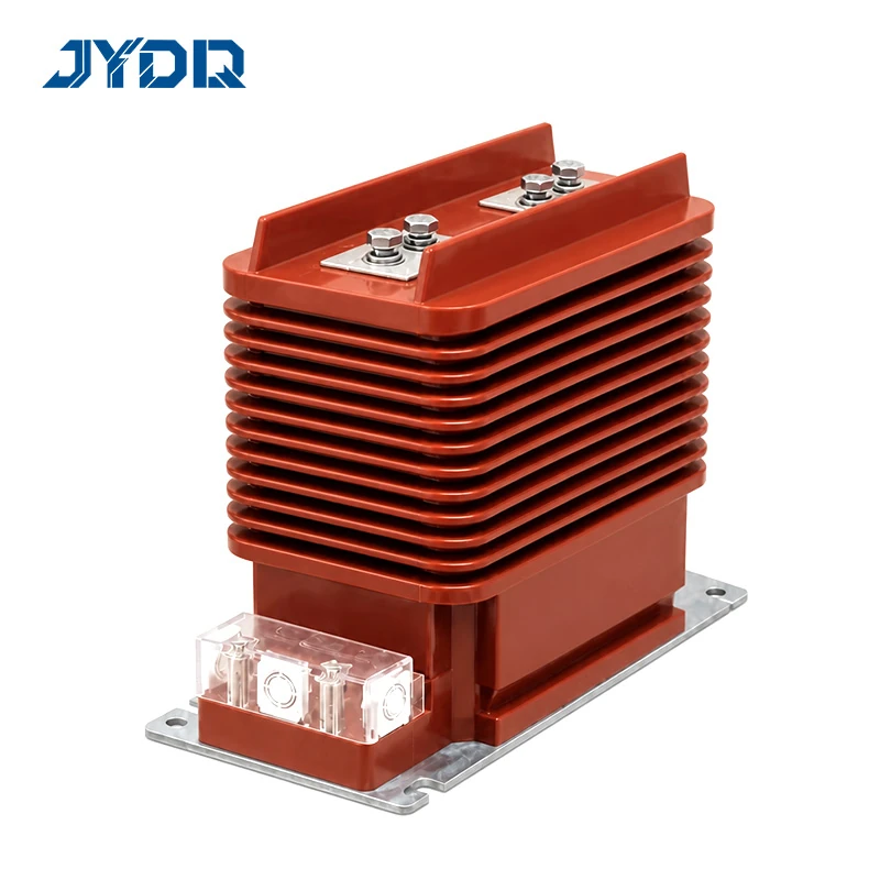
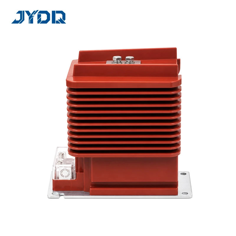
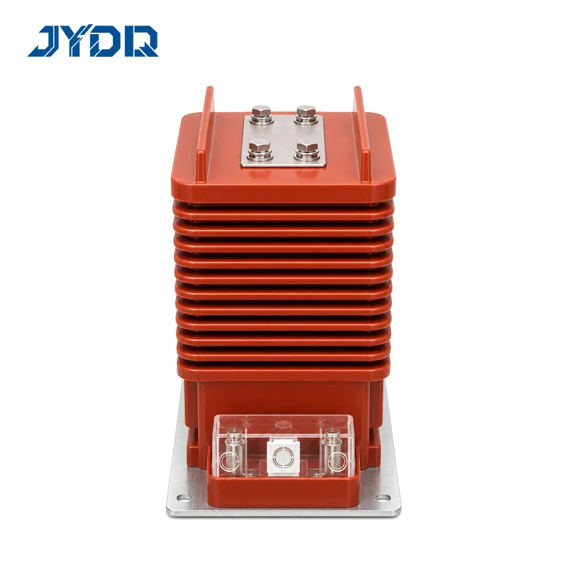
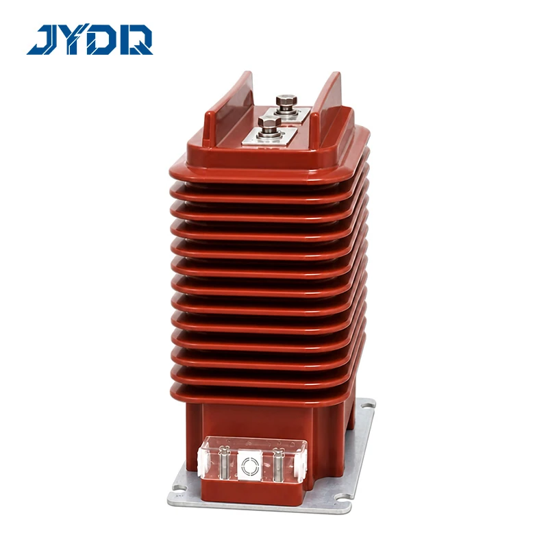
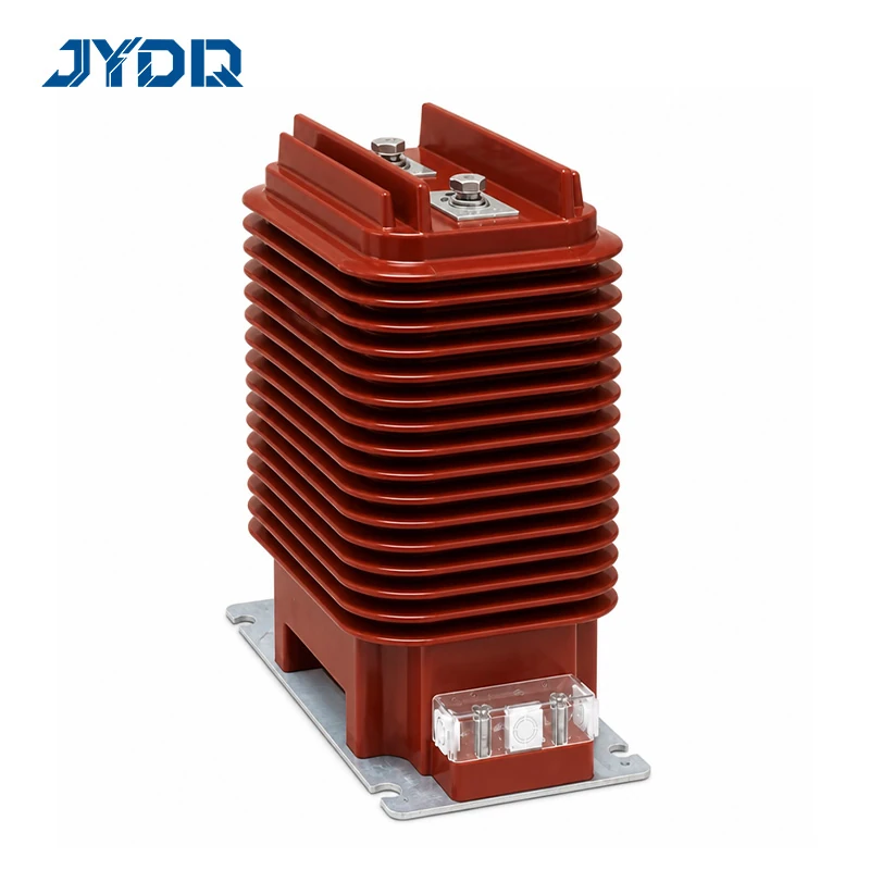
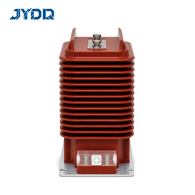
24kV; Accuracy 0.2(S)/10P10 and 0.2(S)/10P15; Output 10-30VA; 1s Thermal 31.5-100kA; Dynamic 80-160kA
This LZZB9-24 series is a post-mounted, cast-insulated current transformer family intended for indoor metering and protective circuits on equipment classified at 24 kV. Published alternatives are LZZB9-24/180b/2, LZZB9-24/180b/4, LZZB9-24/220b/2, and LZZB9-24/220b/4. Each uses P1 and P2 primary terminals. Treat every reference as a selected model plus assigned duty, not as a universally interchangeable catalogue item.
That distinction is important. The LZZB9-24/(18,22)0b/(2,4) 24kV Post-Type Cast-Resin Current Transformer, 180b & 220b, Structure 2 & 4 is a family designation, not a finished order specification. A 180b or 220b designation and a structure 2 or 4 code are part of model identity, but they do not by themselves establish the required primary current, secondary arrangement, accuracy class, protection class, rated output, fault duty, or mechanical interface. Start with the protection and metering duties, then confirm the applicable row in the selected model table and final technical drawing.
When comparing cast resin transformer advantages against alternative insulation technologies, this design offers excellent dielectric strength, high mechanical endurance, and reduced maintenance. However, these advantages do not replace the need for a precise electrical and mechanical interface review for every project.
The 180b alternatives publish primary-current groups from 20–150 A through 1000 A and 1200 A. The 220b alternatives include those groups and also publish a 1500–2500 A group. Secondary output is published from 10 to 30 VA, depending on the exact model and current group. These figures describe a family range; they are not a promise that every value is available in every configuration.
| Selection item | Published family information | What to verify for the order |
|---|---|---|
| Equipment voltage | 24 kV | Project voltage classification and insulation coordination |
| Nominal-width choice | 180b or 220b | Selected model, busbar arrangement, and compartment interface |
| Structure choice | 2 or 4 | Required secondary circuits and selected table row |
| Primary-current groups | 180b: 20–150 A through 1000 A and 1200 A; 220b also: 1500–2500 A | Required rated primary current |
| Rated output | 10–30 VA | Output associated with the exact class and current group |
| Primary terminals | P1 and P2 | Connection orientation in the approved drawing |
For the 20–150 A group, the published one-second thermal value is 150Iin and the rated dynamic value is 375Iin. For higher listed ranges, published one-second thermal values run through 31.5, 45, 63, 80, and 100 kA, while published dynamic values include 80, 112.5, 130, and 160 kA. Read each fault value with its associated rating row. It is not technically sound to carry a value from one current group to another solely because both belong to the LZZB9-24 family.
The published 180b combinations include 0.2(S)/0.2, 0.2(S)/0.5, 0.2(S)/10P10, 0.5(S)/10P10, 0.2(S)/10P15, and 0.5(S)/10P15. Published 220b combinations include 0.2(S)/10P10/10P10, 0.5(S)/10P10/10P10, 0.2(S)/10P15/10P15, and 0.5(S)/10P15/10P15. Availability still depends on the chosen configuration.
Higher nameplate values do not automatically mean a better project result. The useful selection is the one whose published class, output, fault duty, and physical interface match the actual circuit. This is especially relevant when metering burden, relay coordination, and secondary wiring must operate as one protection system. Proper coordination with downstream devices such as a contactor and overload relay ensures the complete electrical protection scheme operates correctly.
Use the published dimensions only for preliminary layout and use the approved drawing for installation control. The 180b/2 drawing indicates a 300 mm upper width with a 345 mm base. The 180b/4 drawing indicates a 420 mm upper width with a 465 mm base. For the 220b alternatives, the supplied references show a 420 mm upper width, 280 mm body height, and 465 mm base. Confirm the drawing revision for exact order line.
Base drilling changes with the current arrangement. The supplied material states four M12 holes for 20–1250 A arrangements and eight M12 holes for the 1500–2500 A arrangement; the higher range is listed for 220b models. A sound compartment review also considers cable approach, terminal reach, service clearance, adjacent parts, and the direction-A drawing. An outline dimension alone does not establish fit.
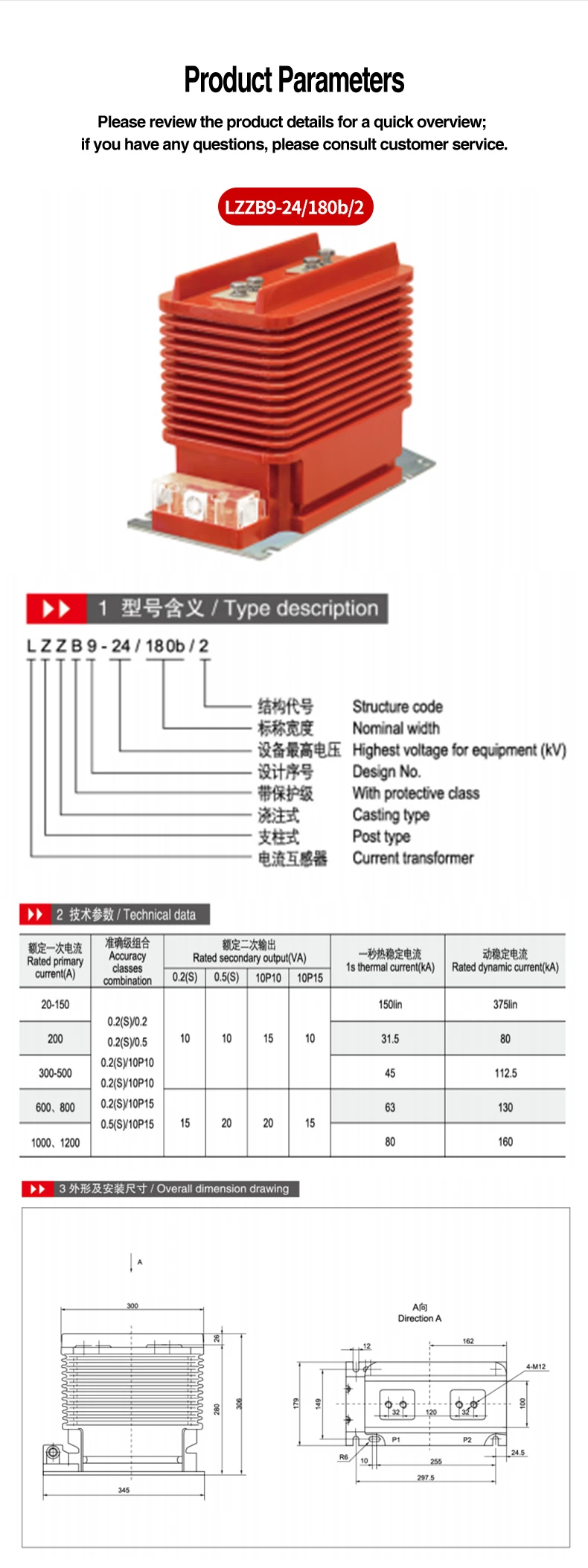
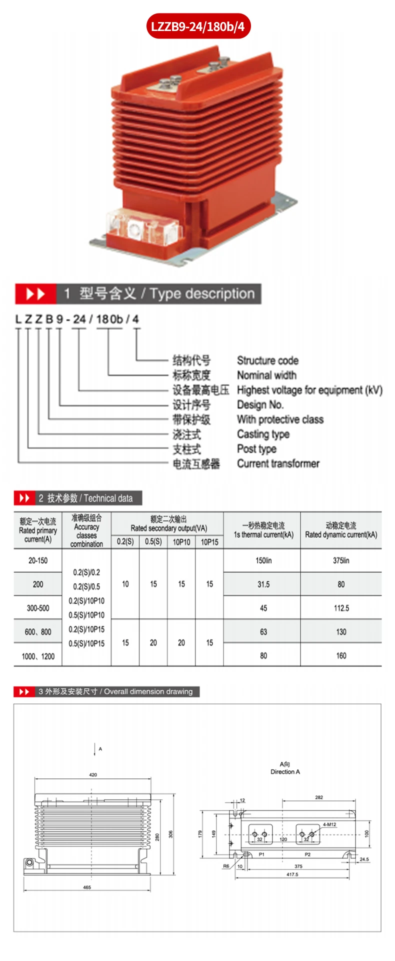
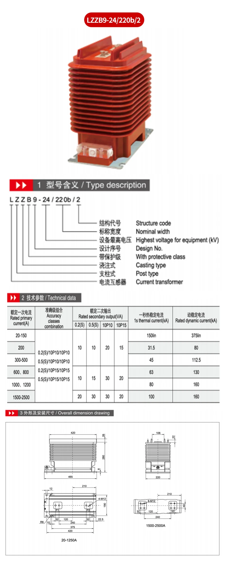
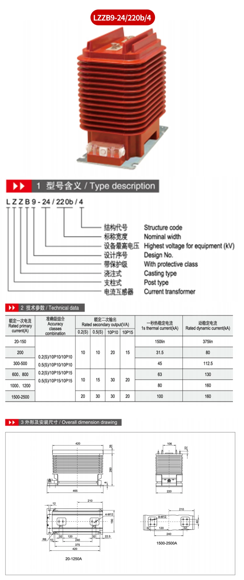
Evaluate this indoor family when a 24 kV measurement or protection circuit needs a configuration supported by applicable published table. Examples can include metering circuits requiring an available 0.2(S) or 0.5(S) arrangement; protection circuits needing an applicable 10P10 or 10P15 arrangement with matched fault data; and selected 220b options for which two protective-class outputs are listed. These examples guide specification review and do not establish suitability without the selected data row.
For indoor electrical rooms, the cast-resin construction can be relevant to an equipment review, but the final decision must account for the complete installation conditions and approved project requirements. A pole-mounted fuse is not a supplied feature or accessory of this indoor transformer listing; if it is part of an upstream or downstream scheme, coordinate it as a separate engineering item.
Provide the required model, rated primary current, metering and protective classes, rated secondary output, secondary-circuit requirement, mounting constraints, and requested documents. State whether the project requires the 1500–2500 A arrangement, since that range is linked in the supplied material with the 220b variants and the eight-hole base arrangement. Where space or cable access is restricted, request the final outline and mounting details for approval before fabrication.
The supplied product information lists MOQ 1, T/T payment terms, and delivery within 20 days after payment is received. Confirm the selected-model data, commercial terms, availability, and documentation in the inquiry. A clear technical schedule helps align a quotation to actual measurement and protection duty rather than to a general family description.
24kV; Accuracy 0.2(S)/10P10 and 0.2(S)/10P15; Output 10-30VA; 1s Thermal 31.5-100kA; Dynamic 80-160kA

 EN