Successful deployment of a prefabricated box-type transformer requires careful coordination of multiple technical documents. Each drawing serves a distinct purpose in the design, installation, and operational lifecycle of your substation equipment. Understanding which drawings matter most ensures your project stays on schedule, meets regulatory requirements, and functions reliably from day one.
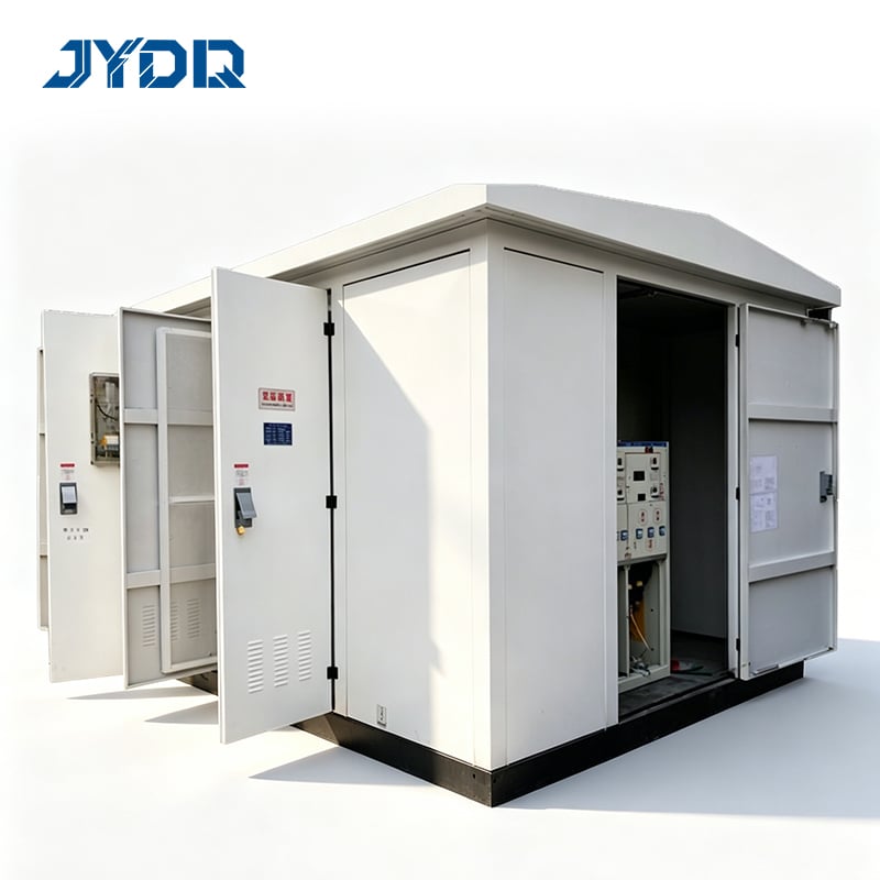
A prefabricated box-type transformer combines the transformer, switchgear, and protection equipment into one factory-assembled unit. This integration simplifies field installation but demands comprehensive documentation. Electrical engineers, project managers, and installation crews all depend on accurate technical drawings to execute their roles correctly. Missing or incomplete documentation can lead to costly delays, safety risks, and performance issues.
Single Line Diagram and Electrical Configuration
The single line diagram stands as the foundation of electrical project documentation. This drawing depicts how the prefabricated box-type transformer connects within your distribution network, showing transformer ratings, feeder lines, protection devices, and control circuits. It provides a clear schematic view that electricians and engineers use to verify the transformer specifications match project requirements.
Understanding Single Line Diagram Requirements
Your single line diagram must include transformer capacity, voltage ratings, impedance values, and protective relay settings. The diagram should clearly mark primary and secondary sides, neutral grounding details, and any load connection points. This technical drawing ensures that protection coordination aligns with utility standards and customer demands. Without an accurate single line diagram, field crews cannot verify correct wiring sequences or test protection settings properly.
Coordination with Protection Settings
The single line diagram directly informs your relay configuration and fusing strategy. When a prefabricated box-type transformer arrives on site, installation crews cross-reference the single line diagram against the unit's internal wiring and nameplate data. Misalignment between the diagram and actual transformer specifications invites operational failures and potential safety hazards. Detailed single line diagrams prevent these costly mistakes by creating a shared reference point for all stakeholders.
Layout and Site Installation Drawings
Layout drawings define the physical placement of your prefabricated box-type transformer and surrounding infrastructure. These technical drawings specify foundation dimensions, cable entry points, ventilation clearances, and utility access routes. Accurate layout planning ensures proper cooling airflow, safe maintenance access, and compliance with local electrical codes.
Foundation and Ground Preparation Details
The layout drawing includes foundation specifications, soil bearing capacity requirements, and anchor bolt positioning. Your construction team uses this technical drawing to prepare the site before the transformer arrives. A properly engineered layout prevents settling, misalignment, and vibration issues that would degrade transformer performance. The drawing should specify concrete thickness, reinforcement patterns, and drainage provisions to protect the prefabricated box-type transformer from moisture and environmental stress.
Cable Routing and Connection Points
Layout drawings identify entry points for incoming and outgoing cables, duct bank locations, and conductor routing paths. This ensures your electrical crew can plan conduit runs, cable sizing, and termination locations before installation begins. Proper cable routing reduces voltage drops, minimizes electromagnetic interference, and simplifies future maintenance access. When layout drawings are complete and accurate, site logistics become predictable and efficient.
Additional Critical Technical Documentation
Beyond the single line diagram and layout, several other technical drawings deserve careful attention. Three-line diagrams, control circuit schematics, and equipment connection details round out the documentation package needed for a prefabricated box-type transformer installation.
Three-Line Diagrams and Control Circuits
Three-line diagrams show all three phases and neutral separately, providing greater detail than single line representations. This technical drawing becomes essential when specifying load balancing, neutral grounding practices, and phase rotation requirements. Control circuit schematics detail the logic for protection relays, circuit breaker trip coils, and alarm signaling. These drawings ensure your prefabricated box-type transformer operates within design parameters and responds appropriately to fault conditions or overload scenarios.
Equipment Nameplate and Specification Drawings
Nameplate drawings document transformer ratings, connection configurations, and factory test results. These technical drawings serve as the contract baseline between equipment manufacturer and customer. They confirm that the prefabricated box-type transformer delivered to your site matches the specifications in your purchase order. Specification drawings also include cooling system details, insulation materials, and noise level certifications that inform operation and maintenance planning.
FAQ
Why is the single line diagram essential before installing a prefabricated box-type transformer?
The single line diagram creates a unified electrical reference that guides design verification, protection coordination, and field testing. It ensures that transformer ratings, fault current capacity, and relay settings align with system requirements. Without this technical drawing, installation crews cannot confidently connect the prefabricated box-type transformer or validate that protection devices will operate correctly during fault conditions.
What does a layout drawing accomplish for a prefabricated box-type transformer project?
Layout drawings specify physical dimensions, foundation requirements, cable access routes, and ventilation clearances. They transform the site from an undefined space into a prepared location ready for equipment installation. This technical drawing prevents costly rework caused by inadequate foundations, improper cable routing, or insufficient cooling clearance around the prefabricated box-type transformer unit.
How do technical drawings reduce project risk and delays?
Complete technical documentation eliminates guesswork and allows teams to identify conflicts before installation begins. When engineering, procurement, and construction teams all reference the same accurate drawings, misunderstandings disappear. These shared technical drawings serve as dispute resolution tools and compliance records that protect your organization throughout the prefabricated box-type transformer lifecycle, from commissioning through retirement.

 EN