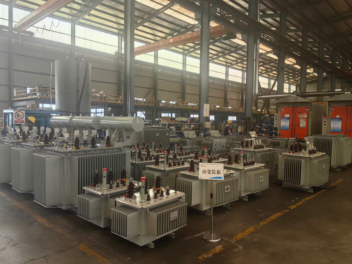
High and low voltage switchgear works in coordination with transformers to manage electrical distribution safely and efficiently across power systems. The relationship between switchgear and transformers is fundamental to modern electrical infrastructure, particularly in substations where voltage levels change and power must be distributed reliably. Understanding this integration is essential for engineers, facility managers, and anyone responsible for maintaining electrical systems that serve industrial, commercial, or utility-scale operations.
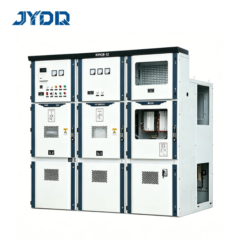
The operational success of any substation depends on precise coordination between switchgear components and transformer units. When electrical current flows through a system, the transformer steps voltage up or down depending on distribution requirements, while the switchgear integration ensures protection, isolation, and proper routing of that current. This article explores the mechanisms, design principles, and practical considerations that make this partnership work seamlessly in real-world electrical networks.
Fundamental Operating Principles of Switchgear and Transformer Coordination
How Voltage Transformation Relates to Switchgear Function
A transformer converts electrical voltage from one level to another through electromagnetic induction, while high and low voltage switchgear manages the flow and protection of current at different stages. In a typical substation, incoming transmission voltage enters switchgear equipment designed to handle high voltage levels. The transformer then steps this voltage down to a medium or low voltage suitable for distribution to end users or downstream equipment. The switchgear on the output side of the transformer must be rated and configured for the lower voltage while maintaining protection coordination with upstream components.
Switchgear integration in this arrangement serves multiple critical functions simultaneously. It isolates circuits for maintenance, interrupts fault currents that could damage equipment, and directs power along intended paths. The transformer, in turn, provides voltage adjustment that allows different parts of the electrical system to operate at their designed voltage levels. Without proper coordination between these elements, voltage instability, equipment damage, and operational inefficiency become likely outcomes.
Protection Coordination Between Components
Protection coordination ensures that if a fault occurs in the system, the nearest switchgear device trips first, isolating only the faulted section while keeping the rest of the network operational. Transformers have inherent impedance that affects how fault current flows, and high and low voltage switchgear must be designed with this impedance in mind. Protective relays and sensors in the switchgear equipment sense abnormal conditions and send trip signals to breakers, which then open circuits to prevent cascading failures.
The relationship between transformer impedance and switchgear protection settings is not arbitrary. Engineers calculate the fault current levels that will occur at different points in the system, then select switchgear with appropriate interrupt ratings and calibrate protection schemes accordingly. This calculation is central to substation design because undersized or improperly coordinated switchgear cannot interrupt fault currents safely, leading to potential explosions, fires, or widespread outages.
Design Architecture of Substations Integrating Switchgear and Transformers
Substation Layout and Equipment Arrangement
A typical substation layout includes high voltage switchgear on the incoming side, a transformer bank in the center, and medium or low voltage switchgear on the output side. This arrangement is called a 'primary-transformer-secondary' configuration and is the most common topology for voltage step-down applications. The spacing, grounding, and isolation distance between high voltage switchgear components must meet stringent safety standards because of the higher energy levels present at those voltage ratings. Low voltage switchgear on the secondary side can be more densely packed because lower voltages pose reduced arc flash and personnel safety hazards.
The physical proximity of switchgear and the transformer must balance several competing requirements. They must be close enough to keep cables short and reduce voltage drop, yet far enough apart to ensure safe working distances and allow for heat dissipation. Transformer cooling requires proper ventilation, and switchgear needs adequate space for operation and maintenance. Substation designers also consider cable routing, control wiring for protective relays, and future expansion when planning layout. The switchgear integration strategy used depends on whether the substation is outdoor, indoor, or a hybrid configuration.
Cable and Bus Configuration
High and low voltage switchgear connects to transformers through heavy-gauge cables or rigid bus conductors designed to carry full load current without excessive voltage drop. The cable or bus size is determined by the transformer's rated capacity and the distance between switchgear and transformer. Undersized conductors create heating losses and voltage regulation issues; oversized conductors increase cost and installation complexity. Most substation designs use aluminum or copper bus bars for the main connections because they offer excellent conductivity and thermal performance.
Switchgear integration also requires careful attention to grounding and bonding of all conductive surfaces. A solid ground reference prevents dangerous voltage differentials, reduces electromagnetic interference, and protects personnel during maintenance. The transformer core and tank must be grounded, and all switchgear frames must be bonded to the same ground grid. This interconnected grounding system becomes the foundation for protection coordination because it allows fault currents to return safely to their source and enables protective relays to sense fault conditions accurately.
Practical Application and Operational Considerations
Load Monitoring and Control Integration
Modern substations equipped with high and low voltage switchgear and transformers incorporate monitoring systems that track transformer loading, temperature, and performance in real time. These systems send signals to protective relays within the switchgear, which can automatically adjust tap settings on the transformer to maintain voltage regulation as loads change. Switchgear integration with digital control systems has transformed substation operation from purely manual to increasingly automated, reducing human error and improving response times during abnormal conditions.
Operators must understand how the transformer and switchgear respond to different operating scenarios. When load increases, transformer current rises, voltage on the secondary side drops, and the protective relays may signal tap adjustment if the transformer has an on-load tap changer. If a fault occurs, the high voltage switchgear upstream of the transformer will sense the fault condition through its protective relays and open its main breaker, disconnecting the transformer from the source. The low voltage switchgear on the output side will simultaneously open its protective devices to isolate the faulted section from downstream equipment.
Maintenance and Testing Requirements
Proper maintenance of high and low voltage switchgear and transformers extends equipment life and ensures reliable operation. Switchgear contacts must be cleaned and inspected for wear, insulation must be tested periodically, and protective relay settings must be verified against design specifications. Transformers require regular oil analysis to detect early signs of degradation, cooling system performance must be monitored, and winding insulation resistance must be tested to identify moisture ingress or other deterioration.
Switchgear integration testing includes verification that protective relay schemes operate correctly and that switchgear devices open and close reliably under all conditions. These tests are often performed without energizing the equipment by injecting test currents into relay coils and observing that breakers trip at the correct threshold levels. When transformers and switchgear are tested together during commissioning, engineers verify that fault current flows as calculated and that protection coordination works as intended. Regular maintenance following manufacturer recommendations and industry standards ensures that the switchgear integration and transformer coordination remain effective throughout their operational life.
FAQ
Why is switchgear integration with transformers necessary in substations?
Switchgear integration protects transformers and downstream equipment from fault currents, isolates sections for maintenance, and enables voltage regulation to match changing load demands. Without high and low voltage switchgear, transformers would lack protection from short circuits, equipment could be damaged by uncontrolled fault currents, and the electrical system would be unsafe for personnel to operate and maintain. A well-integrated switchgear and transformer system creates a resilient, controlled distribution network that reliably serves end users.
How do protective relays in switchgear coordinate with transformer impedance?
Protective relays detect fault current by measuring voltage and current at multiple points in the system, and the transformer's impedance directly affects the magnitude of fault current that flows. Engineers use these impedance values to calculate the expected fault current at each relay location, then program relay trip settings so that the upstream device opens first, isolating the fault before it propagates. This selective coordination requires detailed knowledge of transformer characteristics and careful calibration of switchgear protection settings to ensure that only the affected portion of the network is disconnected during a fault event.
What are the key safety considerations when working with high and low voltage switchgear and transformers?
The primary safety concern is electrical shock and arc flash hazard from high voltage and the energy stored in large transformers. All work on switchgear and transformers must be performed by qualified personnel following lockout-tagout procedures to de-energize equipment and prevent accidental re-energization. Personal protective equipment rated for the voltage and available fault current must be worn, and sufficient working space must be maintained around switchgear installations. Regular safety training, equipment inspections, and adherence to industry standards protect both personnel and the integrity of the electrical system.

 EN