Effective electrical system protection requires seamless coordination between vacuum circuit breaker devices and protection relays. This coordination ensures that faults are detected and cleared at the right time, in the right location, and with the right speed. Without proper synchronization between your VCB and associated protection relay systems, cascading failures can occur, leading to widespread outages and equipment damage. 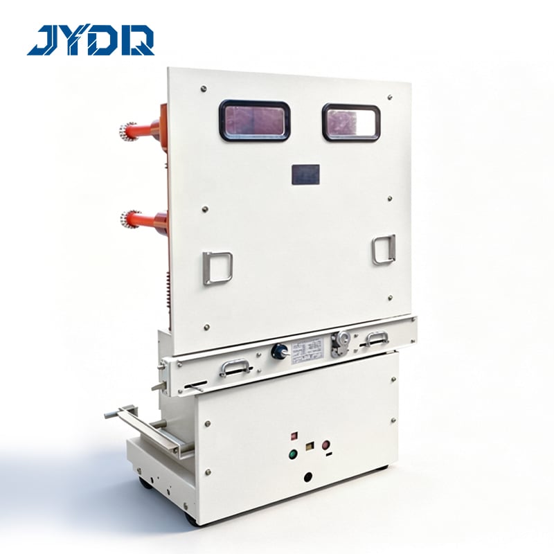
Protection relay technology has evolved significantly over the past two decades, yet the fundamental goal remains unchanged: isolate faulted sections before damage spreads. A VCB paired with modern protection relays creates a robust defense layer in medium and high-voltage systems. The coordination between these components depends on precise time-current relationships, relay selectivity, and backup protection strategies.
Understanding VCB and Protection Relay Fundamentals
The Role of Vacuum Circuit Breakers in System Protection
A vacuum circuit breaker is a mechanical switching device designed to interrupt fault currents in electrical systems. Unlike traditional oil-filled or SF6 breakers, a VCB uses a vacuum arc chamber to extinguish the arc when contacts separate. This design offers several advantages: fast operating times (typically 50-100 milliseconds), low maintenance requirements, compact footprint, and excellent interrupting capacity. In coordination schemes, the vacuum circuit breaker serves as the final isolation mechanism, physically separating the faulted section from the rest of the network.
The speed and reliability of a VCB are critical to successful coordination. When a protection relay detects an abnormal condition—such as overcurrent, ground fault, or phase unbalance—it signals the vacuum circuit breaker to open. The breaker must respond within milliseconds to minimize fault duration and damage.
Protection Relay Functions and Selectivity
Protection relay systems measure electrical parameters continuously and execute pre-programmed logic to detect faults. These devices operate on time-current characteristics that define when and how quickly they will activate a trip signal to the vacuum circuit breaker. Selectivity—the ability of a protection relay to identify which device should open—is fundamental to coordination. Without selectivity, unnecessary breakers open, causing broader outages than necessary.
Numerical protection relays offer programmable time delays, adjustable pickup thresholds, and communication capabilities that enable sophisticated coordination strategies. These relays can distinguish between temporary transients and sustained faults, apply zone-based protection logic, and even communicate with upstream or downstream devices. The coordination of these relay settings with the mechanical characteristics of the vacuum circuit breaker determines the overall protection system's effectiveness and the duration of any service disruption.
Coordination Principles and Methods
Time-Current Coordination Curves
Coordination between a VCB and protection relay relies on the relationship between fault current magnitude and the time required for each device to respond. Engineers use time-current characteristic (TCC) curves—also called coordination curves—to visualize this relationship. The downstream protection relay curve must sit below and to the left of the upstream vacuum circuit breaker curve on a log-log graph. This positioning ensures that the downstream relay operates first during a fault in its zone.
Creating proper coordination curves requires calculating fault currents at multiple points in the network, then adjusting protection relay time dials and pickup settings to achieve the desired selectivity margins. A typical coordination safety margin is 0.3 to 0.5 seconds at maximum fault current. This means the downstream protection relay must complete its operation at least 0.3 seconds before the vacuum circuit breaker operates.
Zone-Based Protection Strategy
Zone-based coordination divides the electrical network into overlapping protective zones, each controlled by a specific protection relay and vacuum circuit breaker pair. Primary protection operates within the intended zone, while backup protection from adjacent zones provides redundancy if the primary device fails. This layered approach prevents total system blackout and ensures that faults are cleared even if one protection relay malfunctions.
The VCB at each zone boundary serves as the isolation mechanism when the protection relay detects an out-of-zone fault. Coordination among multiple zones requires meticulous calculation of relay pickup settings, time delays, and the operating characteristics of each vacuum circuit breaker. Digital relays with communication protocols allow dynamic zone reconfiguration and enable protection schemes that adapt to changing network topology, such as during maintenance or reconfiguration.
Coordination Calculations and Verification
Proper coordination starts with a detailed one-line diagram showing all generation sources, transformers, cables, protection relays, and vacuum circuit breaker locations. Engineers calculate the three-phase fault current and minimum single-phase-to-ground fault current at each protection relay location using established network calculation methods. These fault currents define the range of sensitivities for each protection relay. The relay pickup current must be set above the maximum normal load current but below the minimum expected fault current in its zone to avoid nuisance trips.
Once pickup settings are established, time delay settings are adjusted to achieve the required coordination margins. Computer-aided analysis tools generate TCC curves for all protection relays and associated vacuum circuit breaker devices, allowing engineers to visually confirm selectivity. Any violations of coordination requirements are identified, and relay settings are iteratively refined until the system meets protection objectives.
Practical Implementation and System Design Considerations
Relay Setting Selection and Device Compatibility
Selection of appropriate protection relay models and their settings is the first step toward successful coordination with your vacuum circuit breaker. Modern numerical relays offer independent control of multiple protection functions—phase overcurrent, ground overcurrent, thermal overload, and negative sequence—each with separate time dials and pickup levels. Before finalizing relay settings, verify that the relay's output contacts are compatible with the vacuum circuit breaker's trip coil voltage and current requirements. Typical trip coil voltages range from 24 volts DC to 250 volts DC; ensuring proper voltage matching prevents misoperation or nuisance trips.
Current transformer (CT) ratio selection impacts protection relay sensitivity and coordination. A CT with too high a ratio may cause the relay to be insensitive to faults; a ratio that is too low can cause false alarms from normal inrush currents or transient disturbances. Standard CT ratios are chosen so that the relay pickup setting, when multiplied by the CT ratio, produces a reasonable operating point relative to system fault currents.
Testing, Commissioning, and Maintenance
After installation and before energizing the system, comprehensive testing of coordination between the protection relay and vacuum circuit breaker is mandatory. Injection testing simulates fault currents by injecting calibrated AC or DC current into the relay's input circuit, confirming that the relay trips at the designed pickup current and operates within specified time windows. Trip coil continuity tests verify that the control wiring between the protection relay and VCB is intact and properly connected.
Ongoing maintenance preserves coordination effectiveness throughout the equipment's operational life. Periodic inspection of the vacuum circuit breaker's contact condition, operating mechanism, and insulation resistance identifies degradation before it compromises performance. Protection relay firmware updates and recalibration may be needed if network changes occur, such as new generation sources or transformer additions.
Coordination Under Abnormal System Conditions
Real electrical networks often operate under conditions that differ from ideal three-phase balanced assumptions. Load asymmetry, capacitor bank switching, and starting of large motors create transient currents that may approach normal relay pickup settings. A well-designed coordination scheme must distinguish between these transient events and genuine faults. Protection relays equipped with rate-of-change-of-current detection or harmonic analysis can ignore transients while detecting sustained faults.
Backup protection ensures coordination remains effective if primary protection fails. If a protection relay does not trip within its intended time window, an upstream relay and VCB combination must provide backup isolation, typically within 1 to 2 seconds. This backup strategy uses longer time delays to allow primary devices to operate first, clearing faults before they propagate upstream.
FAQ
What is the minimum coordination safety margin between a protection relay and vacuum circuit breaker?
Industry practice recommends a coordination safety margin of 0.3 to 0.5 seconds. This margin ensures that the downstream protection relay completes its operation—from fault detection through signal transmission to the VCB trip coil—before the upstream breaker responds. The exact margin depends on relay type, VCB model, and application requirements.
Can a single protection relay coordinate with multiple vacuum circuit breakers?
Yes, a single protection relay can manage coordination with multiple vacuum circuit breakers in cascade or ring configurations, provided that fault sensing is positioned correctly and time delays are properly graded. In cascade arrangements, the relay sends trip signals to sequentially more distant VCBs with increasing time delays, ensuring that the nearest breaker opens first.
How do network changes affect coordination between a VCB and protection relay?
Network expansion, such as adding new generators or reconfiguring transformers, alters fault current levels throughout the system. These changes can violate existing coordination margins, requiring recalculation of relay pickup settings and time dials. A protection relay's settings may become inadequate if minimum fault currents increase beyond relay sensitivity, or coordination margins may become excessive if fault currents decrease significantly.

 EN