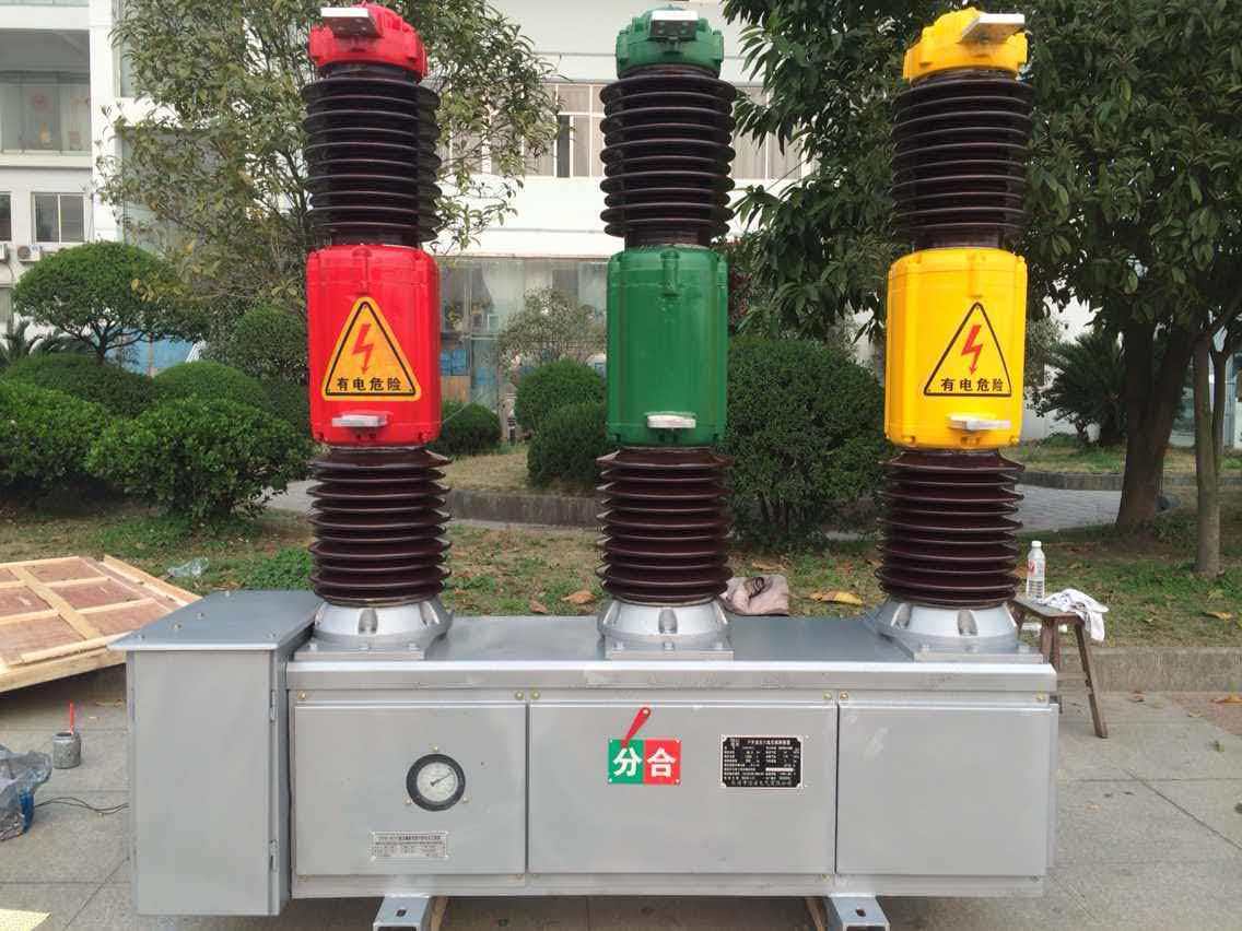
Coordinating circuit breakers in high and low voltage switchgear is a critical engineering practice that ensures reliable electrical system protection and minimizes downtime during fault events. Proper coordination means that when a fault occurs, only the circuit breaker closest to the fault location operates, isolating the problem while keeping the rest of the system live. This selective tripping capability protects equipment, prevents cascading failures, and maintains service continuity across industrial and commercial installations. Without effective protection coordination, a single fault can trigger unnecessary blackouts affecting multiple circuits and connected loads.
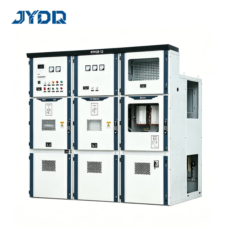
The coordination process involves detailed analysis of current-time characteristics, fault levels, and device settings across your entire electrical network. Engineers must evaluate time-current curves for each breaker, calculate available fault currents at different network points, and ensure proper grading between upstream and downstream devices. This systematic approach requires understanding both the technical fundamentals of circuit breaker operation and the specific requirements of your installation. Success in protection coordination directly impacts system reliability, equipment longevity, and safety compliance.
Understanding Protection Coordination Principles
The Core Concept of Selective Tripping
Protection coordination ensures that electrical faults are interrupted by the nearest protective device without affecting upstream circuits. In a properly coordinated system, downstream circuit breakers operate first, clearing faults in their protected zones. If a downstream breaker fails to clear a fault, the upstream breaker provides backup protection. This hierarchical protection strategy minimizes fault extent and prevents collateral damage to healthy portions of the electrical network. Achieving this requires precise time-current curve alignment and careful coordination across all protection layers.
Time-Current Characteristics and Grading
Each circuit breaker exhibits unique time-current characteristics that define how quickly it responds to different fault currents. The relationship between current magnitude and trip time forms a curve that distinguishes the device's protective behavior. Coordination grading requires that downstream breaker curves remain below upstream breaker curves throughout the operating range, ensuring the downstream device operates first. A safety margin, typically 0.2 to 0.4 seconds, must separate these curves to account for equipment variability and measurement uncertainty. This time buffer prevents nuisance tripping while maintaining system stability.
Designing Switchgear Protection Schemes
Multi-Level Protection in High Voltage Systems
High voltage switchgear typically incorporates multiple protection layers including main breakers, feeder breakers, and differential relays. Each layer must operate within established coordination windows to prevent simultaneous or conflicting operations. Main breakers handle fault currents from the primary supply, while feeder breakers protect individual circuits. Distance relays in transmission systems add geographic awareness by detecting fault location along power lines. In this complex environment, coordination becomes a mathematical and logical challenge requiring advanced analysis tools. Every device must know its role in the protection hierarchy and operate accordingly.
Low Voltage Circuit Breaker Integration
Low voltage circuit breakers within switchgear panels provide the final layer of protection closest to connected loads and equipment. These breakers must coordinate with medium voltage and high voltage protection upstream while responding rapidly to local faults. Standard coordination standards establish maximum clearing times for different fault current ranges. Low voltage breakers typically use thermal-magnetic or electronic trip units with adjustable time delays. Proper setting and coordination of these devices prevents equipment damage and ensures power quality in downstream distribution networks.
Practical Coordination Methods and Tools
Conducting Coordination Studies
A formal protection coordination study begins with detailed electrical network modeling including all generation sources, transformers, cables, and protection devices. Engineers calculate three-phase and single-phase fault currents at every network node using established methods like the per-unit system. These fault current values establish the operating envelope for circuit breaker settings. Time-current curves from manufacturer datasheets are plotted on log-log graphs alongside calculated fault scenarios. The study identifies coordination gaps where breaker curves overlap or provide insufficient safety margins. Each gap requires adjustment of device settings or substitution of alternative breakers to achieve proper selectivity.
Using Coordination Software and Analysis Tools
Modern protection coordination relies on specialized software that automates curve plotting, calculates fault currents, and validates coordination margins. These tools dramatically reduce analysis time and improve accuracy compared to manual methods. Engineers input network parameters, breaker specifications, and desired operating points, then the software generates coordination reports and visual curve diagrams. Sensitivity analysis features allow testing of alternative settings and device configurations without recalculating entire networks. Real-time updates to switchgear settings can be modeled virtually before implementation in the field. Documentation generated by coordination software provides clear evidence of design compliance for audits and regulatory reviews.
Implementation and Field Verification
Setting and Testing Devices
Once coordination studies are complete, technicians must carefully apply the calculated settings to circuit breakers in the actual switchgear installation. Electronic trip units are programmed with specific time delays and current pickup values that implement the coordination scheme. Thermal-magnetic devices require mechanical adjustment of internal calibration components. After physical installation, protective devices undergo field testing including insulation resistance checks, timing verification, and functional trip tests. These tests confirm that devices respond as designed and that coordination objectives are met. Documentation of all settings and test results creates an auditable record for system commissioning and future maintenance.
Ongoing Monitoring and Maintenance
Protection coordination effectiveness depends on maintaining accurate device calibration and promptly addressing any deviations detected during operation. Periodic maintenance schedules should include timing checks to ensure devices remain within acceptable tolerances. If network configuration changes occur—such as adding new generation sources or modifying load distribution—coordination studies must be updated to verify that existing schemes remain valid. Historical trip event data from circuit breakers provides valuable insight into protection performance and reveals any patterns suggesting coordination problems. Regular review of this data helps identify potential issues before they impact system reliability.
FAQ
What happens if circuit breakers are not properly coordinated?
Without proper protection coordination, a fault in one circuit may trigger unnecessary breaker operations throughout the network, causing widespread blackouts affecting areas that should remain unaffected. This cascading failure pattern damages equipment, interrupts critical processes, and increases overall system downtime. Uncoordinated breakers may also allow high fault currents to persist longer than necessary, causing thermal and mechanical stress that reduces equipment lifespan. Safety risks increase when protection does not isolate faults quickly and selectively.
How often should protection coordination be reviewed?
Protection coordination studies should be reviewed whenever significant network changes occur, including addition of new generation, modification of transmission routes, or changes in switchgear configuration. Many facilities conduct comprehensive reviews every three to five years to ensure settings remain appropriate as equipment ages and network conditions evolve. After any major incident involving breaker operation or protection failure, studies should be revisited to identify root causes and prevent recurrence. Regulatory requirements may also mandate periodic coordination audits and documentation updates.
Can coordination be achieved without specialized software?
While small simple networks with few breakers may be coordinated using manual calculations and paper plots, modern industrial and commercial systems are too complex for reliable manual analysis. Specialized coordination software reduces errors, accelerates the study process, and enables scenario testing that manual methods cannot easily accomplish. The software also generates professional documentation required for regulatory compliance and future system modifications. For any system containing more than a handful of protective devices, software-based analysis represents the industry standard approach.

 EN