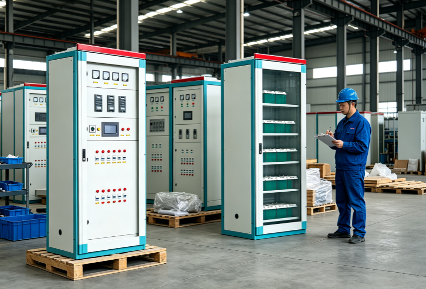
Planning maintenance access around an oil immersed transformer requires careful coordination between equipment placement, operational workflows, and safety protocols. The success of your transformer maintenance program depends heavily on thoughtful initial planning during the installation phase, when decisions about substation layout become permanent infrastructure decisions.
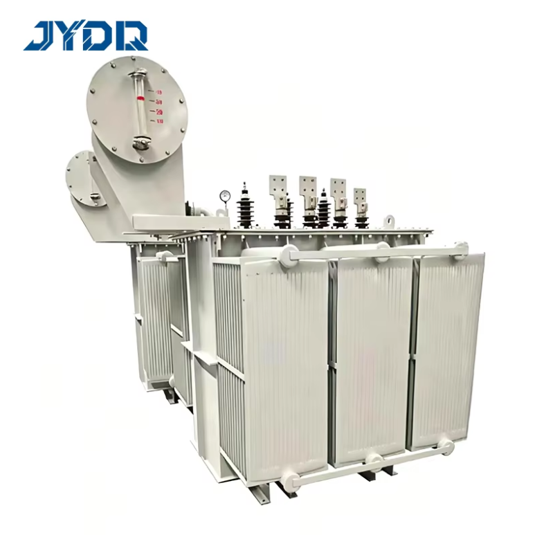
Every oil immersed transformer installed in your facility will eventually require maintenance, whether for routine inspections, oil sampling, component replacement, or emergency repairs. Without adequate maintenance access planning, you risk extended downtime, safety incidents, and operational inefficiencies that compound over time.
Understanding Maintenance Requirements for Oil Immersed Transformers
Core Access Considerations
An oil immersed transformer demands regular maintenance access from multiple angles and heights. Technicians must reach the top of the unit for oil sampling ports, inspection windows, and temperature gauges. Side access is necessary for cooling equipment inspection, valve maintenance, and eventual component service. Bottom access becomes critical when draining oil or replacing internal components during major overhauls.
The physical footprint of your oil immersed transformer extends beyond the tank itself. Include clearance for oil containment systems, which add several feet to the overall space requirement. Your substation layout must account for these peripheral systems while maintaining the maintenance access pathways that technicians rely on during service calls.
Safety Clearance Standards
Industry standards dictate minimum clearance distances around oil immersed transformers for both personnel safety and operational efficiency. These standards exist because maintenance work involves electrical hazards, thermal exposure, and potential oil spillage. When planning your substation layout, incorporate clearance zones that exceed minimum requirements by ten to fifteen percent, creating operational buffer space that accommodates unexpected equipment additions or personnel safety needs.
Strategic Substation Layout Planning for Maintenance Access
Equipment Positioning Principles
Position your oil immersed transformer within the substation layout to create natural access corridors that align with your facility's traffic flow. Place the transformer away from walls or dead-end locations that force maintenance technicians into awkward working positions. Consider how seasonal weather patterns affect your substation layout—rain or snow accumulation can block access pathways if they slope toward the transformer location.
Create a primary maintenance access zone on at least two sides of the installation. This dual-access strategy ensures that if one side becomes temporarily blocked by other equipment or materials, technicians maintain operational flexibility. The substation layout should funnel traffic naturally toward your maintenance staging area, where tools and replacement components can be organized before work begins.
Peripheral System Integration
Your substation layout must integrate cooling fans, oil pumps, and filter carts around the oil immersed transformer without creating congestion zones. These peripheral systems themselves require maintenance access—fan motors need bearing service, pump seals require inspection, and filter units demand regular cartridge changes. Design your substation layout as an interconnected maintenance ecosystem rather than isolated components placed near each other.
Plan adequate space between the transformer and cooling equipment to allow technicians to service cooling components without disrupting transformer operations. This separation also improves heat dissipation efficiency, which extends transformer life and reduces operating costs. During installation, mark these maintenance zones clearly to prevent future equipment placement that would compromise the carefully planned substation layout.
Installation Practices That Enable Long-Term Maintenance Success
Foundation and Ancillary System Design
The installation phase establishes the maintenance access foundation for your oil immersed transformer's entire operational life. Pour concrete pads that extend maintenance access zones evenly on all sides rather than flush against the transformer tank. This installation decision prevents water pooling and creates defined work surfaces where technicians can safely position equipment and materials during service activities.
During installation, route all piping and electrical connections to avoid crossing maintenance access pathways. Overhead cable trays should clear the top of your oil immersed transformer by sufficient distance to allow technicians to work comfortably. These installation details seem minor during the commissioning phase but become permanent constraints during the transformer's twenty to thirty-year operational life.
Documentation and Future Flexibility
Create detailed documentation during installation that records the substation layout precisely, including access clearances, peripheral system locations, and recommended traffic patterns. This documentation becomes invaluable when planning major maintenance work or contemplating substation expansions. Your installation records should identify utilities running beneath concrete pads, overhead obstructions, and any physical constraints that future maintenance teams need to understand.
Build flexibility into your installation by leaving spare ground space in your substation layout that future modifications can use. An oil immersed transformer installation completed with minimal margin becomes difficult to service when new regulatory requirements or equipment upgrades demand additional space. Invest modestly in extra substation layout area during initial installation to avoid expensive reconfiguration projects later.
FAQ
What is the minimum clearance required around an oil immersed transformer for maintenance?
Minimum clearance typically ranges from three to five feet on all sides, depending on your transformer capacity and local regulations. However, best practices recommend increasing this to six to eight feet to provide comfortable working space for technicians and accommodate mobile equipment that may be needed during maintenance activities. Always verify specific requirements with your equipment manufacturer and local utility standards.
How does substation layout planning affect maintenance scheduling?
A well-planned substation layout with optimized maintenance access allows technicians to complete routine service tasks more quickly and safely, reducing unplanned downtime and labor costs. Poor substation layout forces maintenance teams to work in constrained spaces, increasing service duration and operational risk. Better planning directly translates to shorter maintenance windows and improved overall equipment reliability.
Can existing oil immersed transformer installations be modified to improve maintenance access?
Modifications to existing installations are possible but expensive, often requiring equipment relocation, foundation work, and operational downtime. This reality underscores why careful planning during the initial installation phase delivers lasting benefits. If your current installation limits maintenance access, consult with your equipment provider about practical improvements that can be implemented within budget constraints.

 EN