Effective electrical switchgear planning forms the backbone of reliable industrial power distribution systems. When designing infrastructure to support motor loads, engineers must carefully assess multiple technical factors to ensure safety, efficiency, and long-term operational stability. Proper planning prevents costly downtime, equipment failures, and safety incidents that can disrupt production schedules and threaten personnel. This guide walks through the essential steps and considerations for planning electrical switchgear that meets the unique demands of motor load applications.
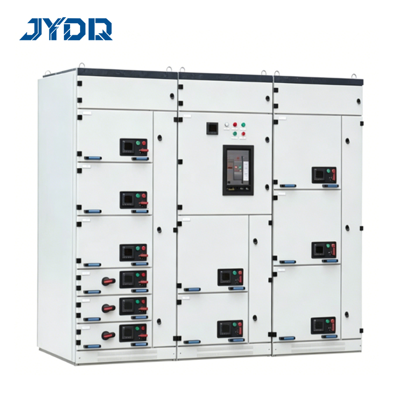
Motor loads present unique challenges in industrial distribution environments because they draw high starting currents, produce reactive power, and require coordinated protection schemes. Understanding these characteristics is fundamental before selecting or configuring your electrical switchgear infrastructure. The stakes are high: undersized equipment causes nuisance trips, oversized equipment wastes capital, and misaligned protection leaves motors vulnerable to damage. Strategic planning ensures your motor load distribution system performs reliably while optimizing operational costs.
Assessing Motor Load Requirements and Characteristics
Understanding Full Load and Starting Currents
Motor loads differ fundamentally from static electrical loads because they draw substantially higher current during startup than during normal running operation. Full load current represents the sustained current draw when a motor operates at rated speed and torque, while starting current can reach five to seven times the full load current during the inrush phase. Planning electrical switchgear requires accurate data on both values because the switchgear must safely handle and interrupt these currents without damage. For an MCC serving multiple motors, you must aggregate full load currents and apply diversity factors to estimate the combined demand that electrical switchgear components will experience.
Calculating Total Connected Load and Demand
Start your planning process by listing every motor that will connect to your industrial distribution network, documenting horsepower, nameplate voltage, speed, efficiency class, and service factor for each unit. Sum the full load currents to determine total connected load, then apply a demand factor that reflects the probability that all motors will run simultaneously at full load. Industrial facilities rarely operate every motor at full capacity at the same instant, so demand factors typically range from 0.7 to 0.95 depending on the application. This calculated demand current directly determines the rating and capacity of the electrical switchgear you select, ensuring it can handle realistic operating conditions without oversizing or undersizing the system.
Selecting and Configuring MCC Solutions
MCC Architecture and Motor Load Organization
An MCC, or motor control center, is the engineered hub for managing multiple motor loads within an industrial distribution system. MCC designs consolidate motor starters, control circuits, power distribution, and protection devices into a modular framework that simplifies installation, maintenance, and troubleshooting. When planning electrical switchgear for motor loads, an MCC provides scalability because you can add starter modules as production requirements expand without redesigning the entire system. Each starter bucket within an MCC connects to an individual motor, with its own contactor, overload relay, and possibly soft-start or variable frequency drive technology, depending on application needs.
Protection and Control Integration
Effective motor load management requires coordinated protection at multiple levels within your electrical switchgear framework. Main incoming breakers protect the overall system, while individual starter protection devices safeguard each motor against overcurrent, phase loss, thermal overload, and short-circuit faults. MCC configurations allow you to integrate auxiliary contacts, signaling lights, and remote monitoring interfaces so operators gain visibility into motor status and fault conditions. Motor load protection schemes must be calibrated carefully so that protective devices respond quickly to faults without nuisance tripping during acceptable starting transients or momentary voltage sags in your industrial distribution network.
Industrial Distribution System Coordination and Planning
Feeder Sizing and Overcurrent Protection Coordination
Sizing feeders that connect electrical switchgear to motor loads requires coordinating conductor capacity with overcurrent protection ratings to ensure safe operation across all fault scenarios. Conductors must handle the combined full load current of connected motors plus a safety margin, while feeder breakers must be sized to accommodate inrush currents from motor starting without nuisance trips. Industrial distribution standards require that protective devices operate in a coordinated sequence so that a fault at a motor starter trips only that individual protection device, leaving other motors supplied by the same electrical switchgear unaffected. This selective coordination prevents cascading failures and maintains production availability for unaffected equipment.
Voltage Drop and Harmonic Considerations
Motor load current creates voltage drop across feeder impedances, which reduces the voltage available at motor terminals and increases motor starting current and heating losses. When planning electrical switchgear and feeder configurations, engineers must verify that voltage drop remains within acceptable limits, typically 3 percent for branch circuits and 5 percent for the combination of service and branch feeders. Additionally, variable frequency drives used with motor loads inject harmonic currents that can interfere with electronic control circuits and increase losses in transformers and electrical switchgear components. Industrial distribution planning must account for harmonic filtering or derating strategies so that your electrical switchgear infrastructure remains stable and reliable even when modern control technologies are deployed alongside traditional induction motors.
FAQ
What is the primary advantage of using an MCC for motor load management?
An MCC provides centralized, modular control of multiple motor loads within a single enclosure, enabling easier troubleshooting, scalability, and coordinated protection across your industrial distribution system. MCC architecture simplifies maintenance and reduces installation time compared to distributed starters, while allowing you to upgrade or add motors without major rework to existing electrical switchgear infrastructure.
How does demand diversity factor into electrical switchgear sizing?
Demand diversity factor accounts for the fact that not all motor loads run at full capacity simultaneously in typical industrial operations. Applying an appropriate diversity factor to full load currents prevents overspecifying electrical switchgear, reducing capital costs while ensuring adequate capacity for realistic peak motor load conditions without undersizing components.
Why is protection coordination critical when planning electrical switchgear for motor loads?
Proper coordination ensures that fault current at one motor starter trips only that starter's protection device, leaving other motor loads supplied by the same electrical switchgear uninterrupted. Without coordination, a single motor fault could cascade into widespread downtime, making selective protection a fundamental requirement for reliable industrial distribution systems.

 EN