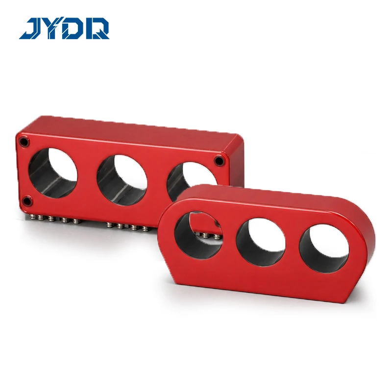
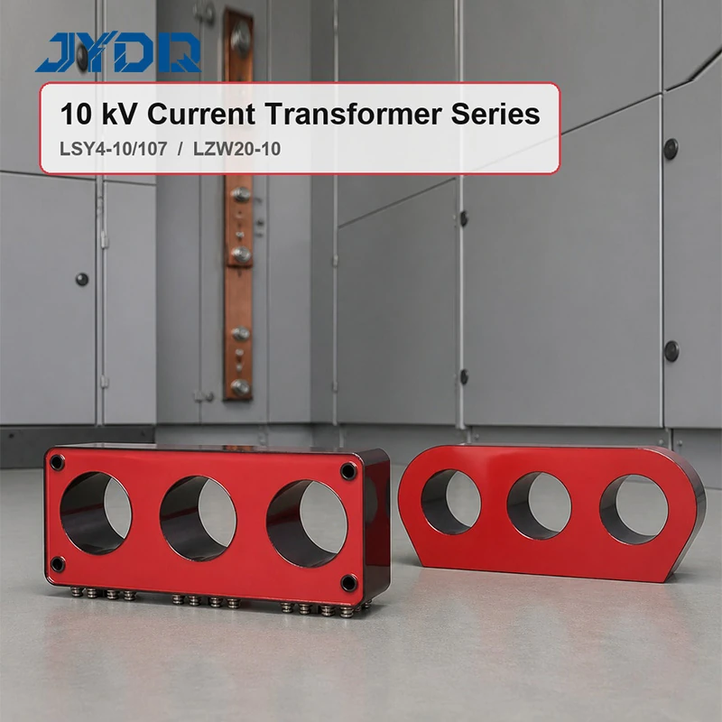
10 kV Current Transformer Family for GIS and Vacuum Breaker Duties
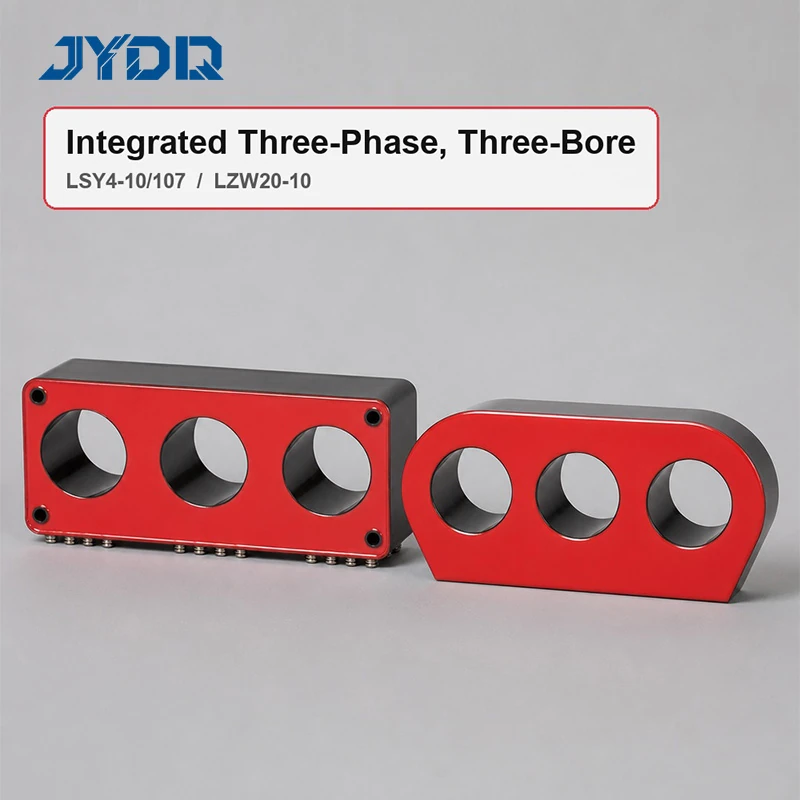
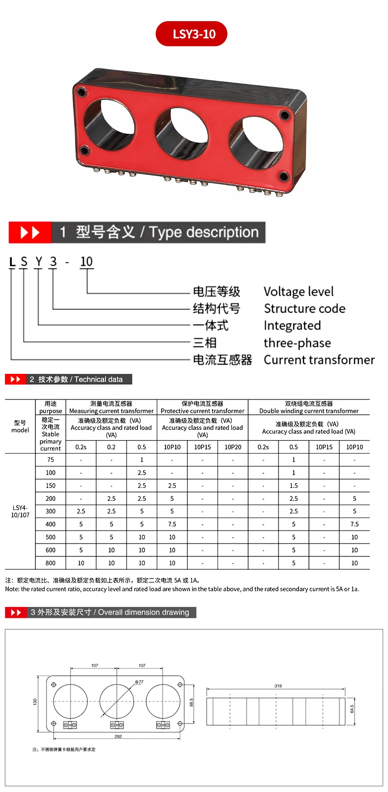
LSY4-10/107 & LZW20-10 10kV Three-Phase Current Transformers for Gas-Insulated Switchgear are two documented configurations intended for three-phase current measurement and protection. They share a 10 kV designation, cast-insulation construction, and a body with three conductor openings. They are not, however, a single interchangeable item. The LSY4-10/107 is an integrated three-phase design. The LZW20-10 is identified in the supplied data as a vacuum-circuit-breaker-oriented model with listed zero-sequence rows. Selection begins with the actual function required by the switchgear, then proceeds to the ratio, secondary circuit, accuracy class, mechanical interface, and protection scheme.
For LSY4-10/107 & LZW20-10 10kV Three-Phase Current Transformers for Gas-Insulated Switchgear, voltage class alone is not a sufficient purchasing criterion. A meter-class current transformer, a protective current transformer, and a multi-ratio arrangement can all look similar during an early layout review, yet they place different demands on the secondary wiring and on the connected relay or meter. Use the product tables as the starting record, then confirm the proposed configuration against the project single-line diagram and the latest approved drawing.
Model Comparison
| Selection item |
LSY4-10/107 |
LZW20-10 |
| Basic form |
Integrated, three-phase, three-bore current transformer |
Three-bore current transformer identified for vacuum circuit breakers |
| Listed primary-current options |
75, 100, 150, 200, 300, 400, 500, 600, or 800 A |
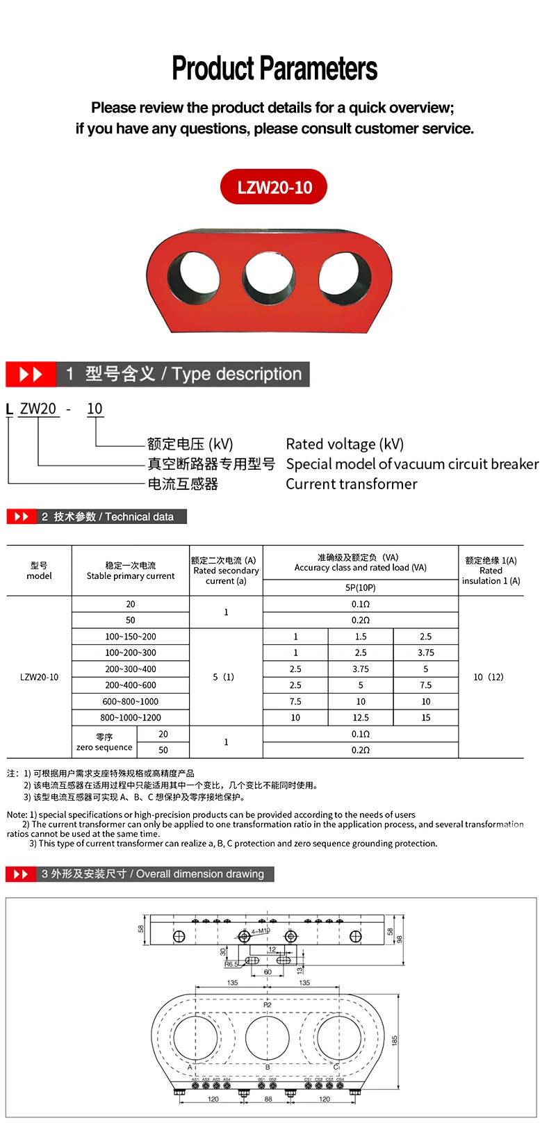
20 A, 50 A, listed multi-ratio groups, and zero-sequence 20 A or 50 A rows |
| Listed secondary current |
5 A or 1 A |
1 A; 5 (1) A for the multi-ratio group |
| Mechanical data |
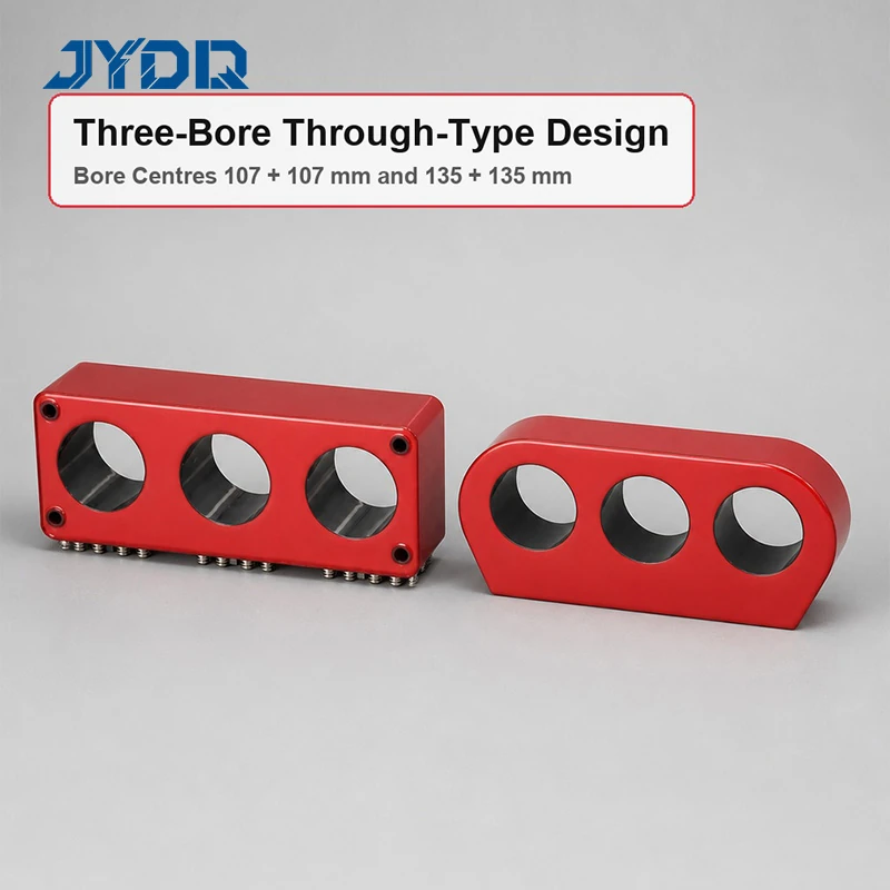
Three Phi 77 mm bores at 107 mm centres; four corner mounting holes |
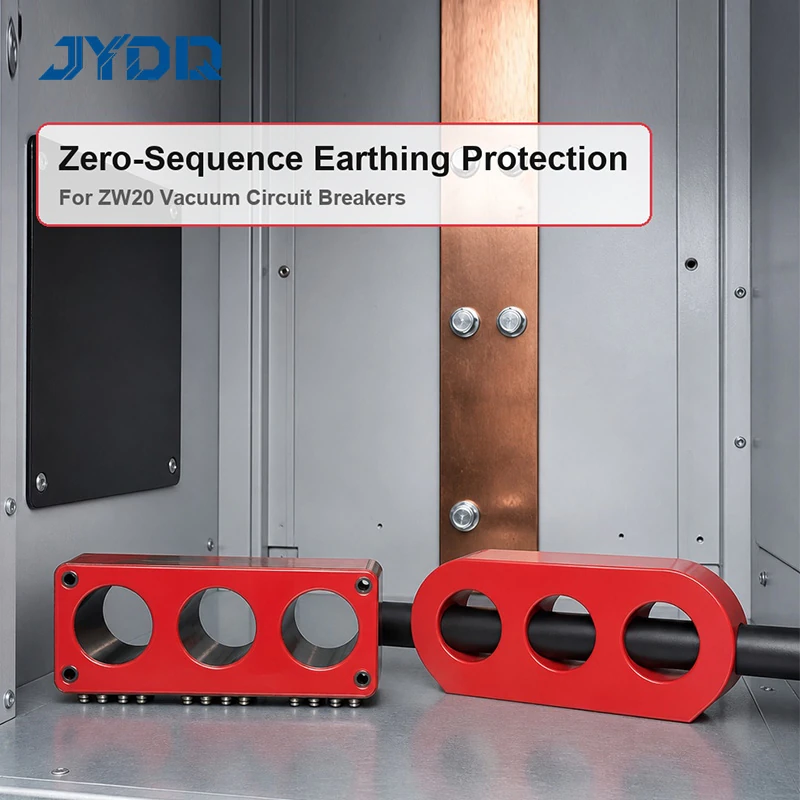
Three phase-marked bores at 135 mm centres; 4-M10 mounting holes |
LSY4-10/107 Selection Notes
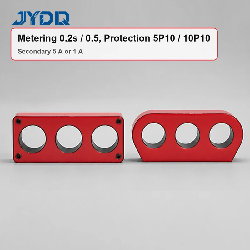
The LSY4-10/107 configuration is the appropriate starting point when an integrated three-phase arrangement is required and the project needs one of its documented rows from 75 A through 800 A. The supplied table lists metering classes 0.2s, 0.2, and 0.5, protective entries 10P10, 10P15, and 10P20, plus double-winding entries. Availability is row-specific. For example, a class appearing at a higher primary current should not be assumed at every lower current. Likewise, a stated rated load belongs to the relevant table entry, not to the whole family.
The three through-bore construction lets phases A, B, and C pass independently through the transformer body. The listed LSY4-10/107 geometry includes three 77 mm diameter openings at 107 mm centres, a 292 mm front-plate width, a 130 mm front-plate height, and a 319 mm block length. These figures assist an initial layout comparison, but conductor clearances, busbar shape, fasteners, enclosure tolerances, and service access still need project verification. If high-precision metering or a nonstandard burden is required, obtain written confirmation for the exact ratio and accuracy combination.
LZW20-10 Selection Notes
The LZW20-10 configuration is documented for vacuum circuit breaker use. In addition to 20 A and 50 A single-current entries, its table lists multi-ratio groups from 100~150~200 through 800~1000~1200 A. The source records class 5P(10P), and it lists rated insulation as 10 (12). It also describes phase protection and zero-sequence grounding protection. Those source statements are helpful selection inputs, not a substitute for an engineered relay-coordination study.
A particularly important boundary applies to its multi-ratio offering: the supplied material says that one transformation ratio may be applied in service and that several ratios cannot be used simultaneously. That condition should be reflected in the wiring design, labels, terminal schedule, commissioning plan, and operating procedure. The table prints 0.1 Ohm and 0.2 Ohm in certain rated-load cells and VA values in others. Rather than reinterpret those entries, confirm their intended unit and the selected burden with the manufacturer before release.
Practical Decision Framework
Start by identifying whether the installation needs the integrated LSY4-10/107 design or the LZW20-10 vacuum-breaker-oriented arrangement. Next, identify the required primary current and the allowed secondary current. Then match the metering or protection duty to the exact source-table row. Finally, compare the bore centres and mounting arrangement with the switchgear assembly. For LSY4-10/107 & LZW20-10 10kV Three-Phase Current Transformers for Gas-Insulated Switchgear, this ordered review avoids treating a family label as a complete specification.
System compatibility deserves the same attention as the unit rating. A current transformer may fit a busbar physically while still being unsuitable for the connected meter, relay, cable run, or protection philosophy. In particular, protection settings must be reviewed across upstream and downstream equipment. If the installation uses zero-sequence protection, establish the measurement objective, grounding arrangement, relay inputs, and test method before finalizing the LZW20-10 selection. If metering performance is the priority, specify the requested accuracy class, burden, ratio, and secondary current clearly.
Typical Uses and Specification Checklist
- 10 kV gas-insulated switchgear where three phase conductors pass through separate current-transformer bores.
- Three-phase measurement or protection circuits requiring a documented LSY4-10/107 current and accuracy row.
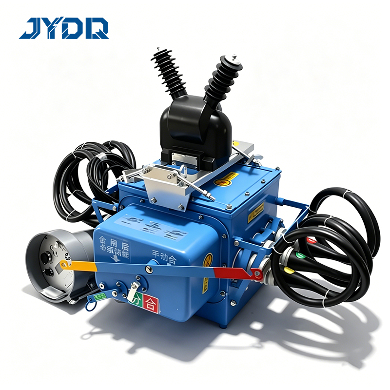
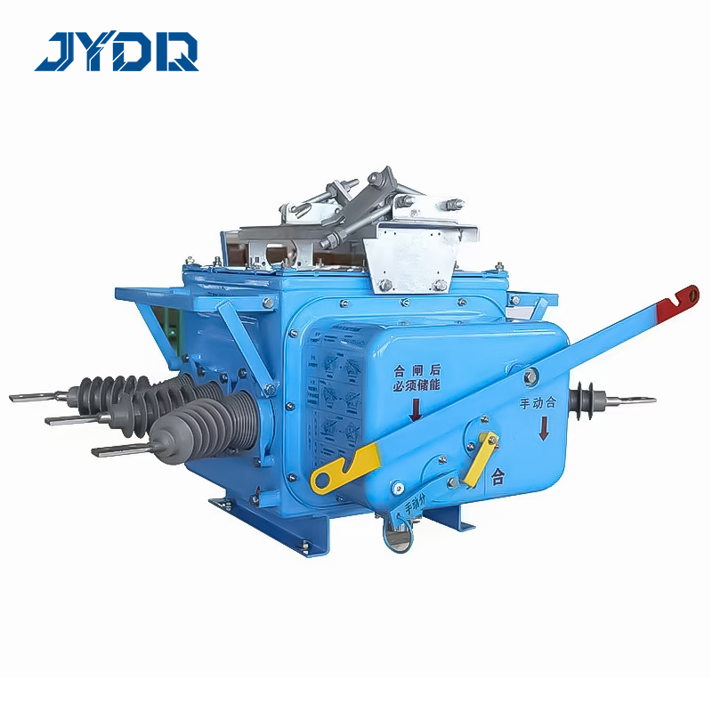
- ZW20 vacuum-circuit-breaker assemblies evaluated against the documented LZW20-10 configuration.
- Systems with a verified need for phase protection and the listed zero-sequence grounding-protection function.
When requesting LSY4-10/107 & LZW20-10 10kV Three-Phase Current Transformers for Gas-Insulated Switchgear, provide the model, primary current, transformation ratio, secondary current, accuracy or protection class, burden, quantity, mounting drawing, conductor geometry, and target switchgear model. Also state whether special specifications or high-precision output is needed. Specify the applicable IEC, IEEE, or local requirement by the project’s confirmed edition and test scope; do not assume compliance merely because a general product family is being considered.
From an engineering perspective, the strongest request for quotation is precise about what must be measured, protected, and physically accommodated. LSY4-10/107 & LZW20-10 10kV Three-Phase Current Transformers for Gas-Insulated Switchgear can then be matched at model and row level, with final drawings and project requirements governing the released configuration.

 EN